What’s New in Material Handling and Blending Systems for Reclaim Extrusion
Keith Larson, Colortronic North America, Inc. — An ACS Group CompanyAbstract
Material handling systems are very important to the proper operation of any extrusion or molding process. An extrusion line is particularly vulnerable because the extruder can only process the material that is being supplied to the system. If the material fed into the feed throat is not blended properly, or at the right rate, the process rate and quality of the final product will suffer because the extruder can only process what goes in.
Manufacturers often spend considerable time on the extruder selection, but throw together pieces of existing or used equipment for a material handling and feeding system. This equipment can be the difference between making money and not, so it is worthwhile to consider what the correct equipment can do for your system:
- Maximum uptime making product
- Accurate feed rates with gravimetric feeders
- Inventory of materials actually used
- Variable speed AC and DC motor controls for improved control and efficiency
- User-friendly PLC-based control systems with color touch screen interfaces for clear communication of status and process data
- New feeders that can handle materials that are difficult to feed
- Gravimetric control of all components through a central interface
Integration with extruder control system for closed loop extrusion control and product weight
The following material handling equipment is crucial to any reclaim extrusion facility:
- Bulk storage of high volume materials
- Handling of sacks and gaylords of additive materials
- Material conveying systems
- Feeding and blending systems Packaging and storage of finished product
This presentation will focus on the first four material handling issues leaving the last item for a separate discussion. Properly configured material handling systems will help produce your product with improved efficiency and lower cost if they are planned out before the system is installed.
Introduction
This paper will focus on the material handling, feeding and blending systems of a reclaim extrusion line, including:
- Material handling and bulk storage of the raw materials
- Material conveying system(s)
- Blending and feeding equipment
Bulk storage of raw material
Bulk storage equipment includes portable storage bins for small amounts of material, and larger surge bins that are generally secured to the floor in a central location. Portable bins are used to store smaller amounts of materials like low-usage virgin materials and additives. Surge bins are often used to moderate virgin material temperatures in colder climates, as well as provide a buffer of virgin and regrind materials inside a processing facility.
Larger amounts of material are stored in welded or bolted silos that can hold up to 250,000 lbs., or more, of material. This allows the processor to buy raw material in truckload or railcar quantities at a reduced price. Savings of $0.05 to $0.10/ lb. are typical, resulting in a strong payback for most large processors.
New features include ultrasonic and infrared level indication, as well as weighing systems to verify material usage.
Pneumatic material conveying systems
Pneumatic (vacuum or pressure) conveying systems are used to move raw materials into a facility, or distribute the virgin, regrind or blended material to molding machines or extruders within a facility.
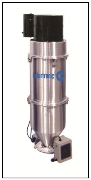
Self-contained hopper loaders include an integral motor that generates the vacuum source. They are often used for lower throughputs of pelletized and clean regrind materials. Special models with extra filtration are also used for dusty regrind or some powder materials.
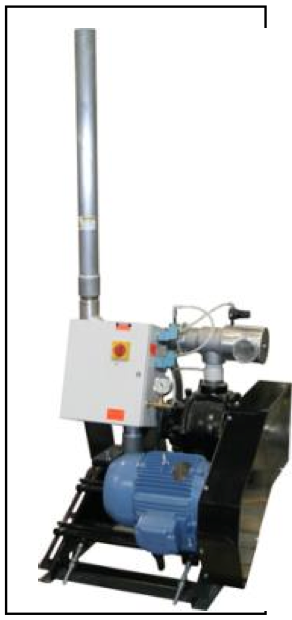
Central vacuum systems are the most common, but pressure systems are often used. These can be a single point-to-point system, like moving resin from a silo to a surge bin, or a from discharge bin on the end of a pelletizing line to the pack-out station. With the proper control system they can sequentially load multiple stations, like a six component blender over an extruder, or load multiple extrusion lines with a common pump.
Most vacuum receivers now use stainless steel mesh screens to keep the pellets or regrind in the vacuum receiver and prevent material carryover to the central filter. The screens will allow dust to carry over to a central filter protecting the vacuum pump. Most of the dust passes through the screen and is collected in the central filter, eliminating maintenance associated with cleaning individual cloth filters on each vacuum receiver.
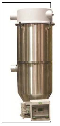
Powder conveying systems utilize better filtration on the receiver itself, keeping the dust and fines in the process. Various methods like “implosion” and compressed air blowback are used to keep the filter cartridges or bags clean, and the system operating at its maximum performance. A simple cartridge style safety filter is usually provided before the inlet on the vacuum pump with these systems. This protects the pump in case a bag in the main filter rips or wears out.
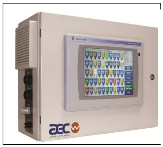
Most conveying systems today use a programmable relay controller (PRC) or a programmable logic controller (PLC) to control the vacuum pumps, sequencing and filter cleaning. The PRC systems are more limited in capability and are usually used for control of one or two pumps and up to 8 loading stations. The PLC systems can handle up to 24 vacuum pumps and 128 stations, and generally include a color touch screen interface with system graphic capabilities. Support documentation, spare parts information, alarm logs and troubleshooting help are often built in.
Some systems integrate multiple systems, like conveying, drying and blending, into one system. While this puts everything in one display, if the controller has a problem, the whole system is down.
Local I/O includes traditional system field wiring and the system must be powered down to add stations or make changes. Distributed I/O technology uses two cables that run through your entire plant, and the modules can be “hot swapped” to add a station of replace a defective one. Installation is much less expensive since conduit is not required – the cables are usually just tie-wrapped to the vacuum line.
Vacuum and pressure power units can be combined into one system to convey high rates of material long distances, like in a rail-car unloading system. The vacuum side pulls the material out of a railcar and discharges it into a cyclone or filter receiver above a rotary valve. A pressure system then blows the material into the storage silo(s).
How to Size a Central Vacuum Conveying System
ExtrusionMaximum process rate of all extruders, plus 50% safety factor
Calculate Actual Conveying Rate:Machine mount blender @ 1,000 lbs./hr.
1,000 x 1 = 1,000 lbs./hr. x 1.5 = 1,500 lbs./hr.
Floor mount blender, then up to extruder
1,000 x 2 = 2,000 lbs./hr. x 1.5 = 3,000 lbs./hr.
Floor mount blender and drying system, then convey up to extruder
1,000 x 3 = 3,000 lbs./hr. x 1.5 = 4,500 lbs./hr.
Add the rate each time the material is conveyed!
Don’t forget the safety factor!
Calculate Equivalent Conveying Distance:
One
horizontal foot =
one equivalent foot
One
vertical foot =
two equivalent feet
Long radius elbow = 20 equivalent feet
One foot
flex hose =
four equivalent feet
Equivalent Feet Conveying Distance Example
100 horizontal feet = 100
20 vertical feet = 40
(4) L R elbows = 80
20 feet of flex hose = 80
TOTAL 300 equivalent feetIt is important to take all of these factors into account and remember the system runs the best when everything is new. As things wear, filters get dirty and connections come loose and leak, the system capacity will decline, so additional capacity up front is a great idea!
Blending and feeding equipment
Blending in the plastics industry meant many things in the past, including pitch forks, shovels, buckets, cement mixers, grain augers and even rolling drums full of material across a plant floor. Volumetric blenders were developed to feed a variety of materials at the same time, and were a leap forward in technology.
Volumetric feeders are still used today, but typically to add only one or two minor ingredients into a process. Many processing facilities use additive feeders to introduce additives into their process. Volumetric and gravimetric feeders are available, with volumetric being the most common.
Volumetric and gravimetric blending systems are available for multiple components, with gravimetric being the most common. Gain-in-weight batch blenders are usually used in injection molding and simple extrusion applications, while continuous loss-in- weight systems are used for high-end extrusion and compounding lines.
Additive Feeders
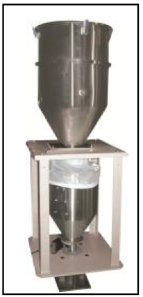
Volumetric feeders are used to add one or two components to a process and are usually the most economical additive feeder you can buy. However, they are strictly a feeder, and even though certain designs are very accurate feeders, none of them can accurately track actual material usage.
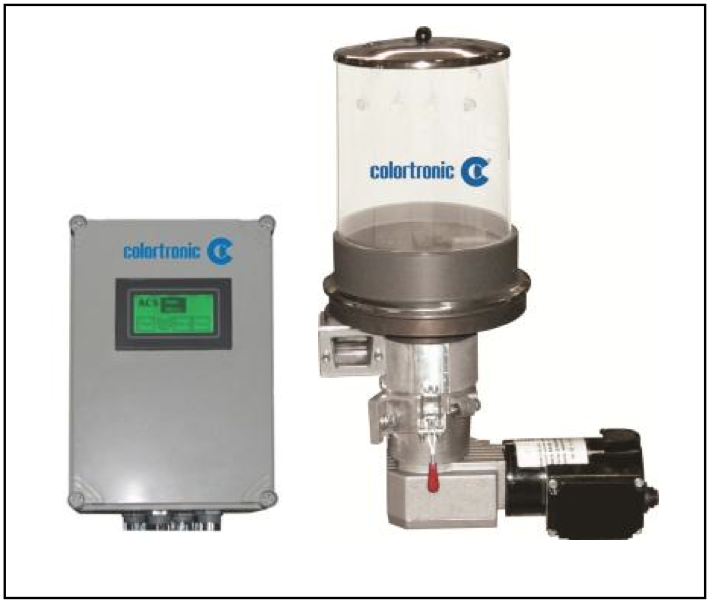
Gravimetric feeders utilize a weighing device to measure the actual throughput that the feeder dispenses, giving the processor an actual measure of the amount of material used. The feeding device may not be as accurate, but the material usage value is, as long as it is properly calibrated to a known weight.
Gravimetric blenders
Gravimetric blenders have come down in price so much that volumetric blenders are almost a thing of the past. Gravimetric blenders provide many advantages, including:
- Improved accuracy
- Compensation for variations in bulk density
- Documentation of correct blending process Inventory control of all blended materials
Virtually all of the gravimetric systems available today offer significant advantages over the volumetric systems. The chart below compares blending processes.
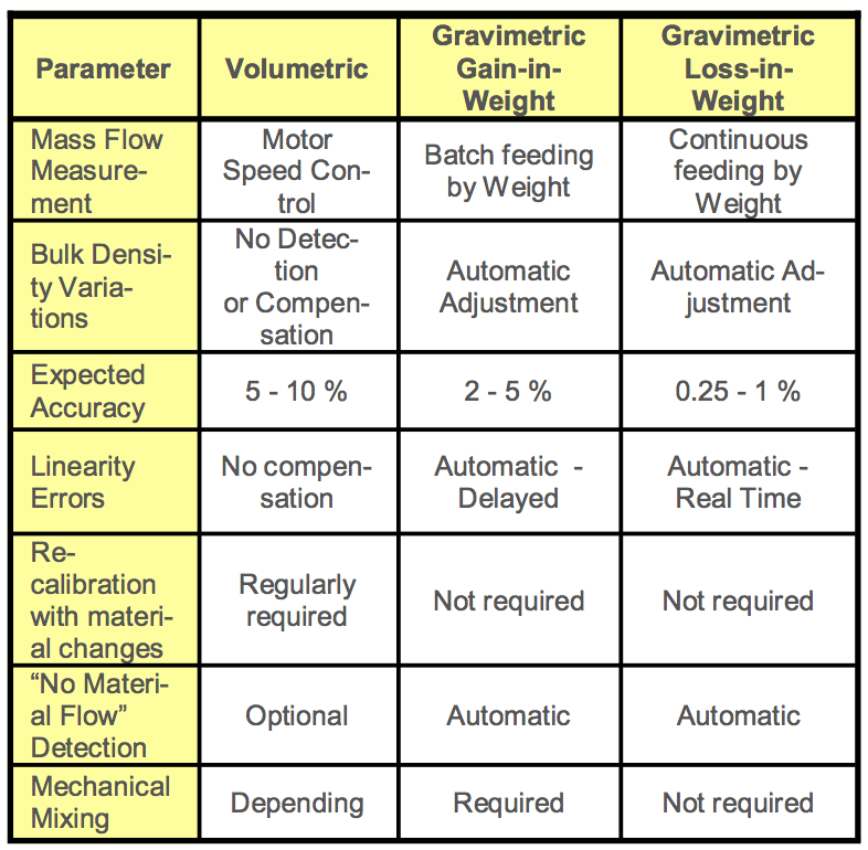
However, there is a lot of confusion about “gravimetric” blending systems, and they are not all the same. In fact, each type works very differently, and has its own advantages and associated costs.
Gravimetric means “to weigh”, but that is where the similarity ends – not all gravimetric systems work the same way, or offer the same advantages. The following types of gravimetric systems are readily available to the processor today:
- Gain-in-weight batch
- Loss-in-weight batch
Continuous loss-in-weight
Gain-in-weight batch blenders weigh one ingredient at a time into a common weigh hopper, mounted on one or two load cells. The batches are dumped into a mix chamber that distributes the components into a homogenous mix. These blenders are very economical, but are not the best choice for low percentage ingredients (< 2%), or materials that vary greatly in particle shape and density, especially powder additives (particles can separate during mixing). These are the most common gravimetric blending systems in use today, are available in up to eight component models and are available from many reliable suppliers.
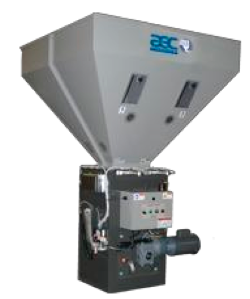
Gain-in-weight Batch Blending Cycle:
The materials are metered one at a time into a common weigh hopper, and each batch is dumped into the mix chamber. The metering cycle repeats, while the mixing continues, until the high level in the mix chamber is reached, and the process stops. Metering will start again when the processing machine draws material from the mix chamber and the level drops below the high level switch.
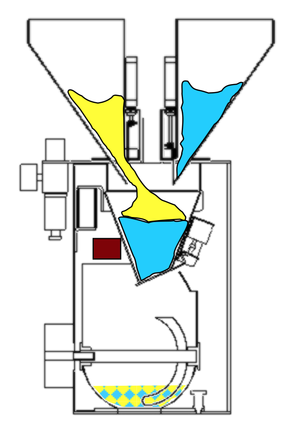
}
Loss-in-weight batch blenders meter all ingredients at the same time into a common collection hopper. Each feeder is equipped with its own load cell so the output of each feeder is constantly controlled. The load cells are sized to each feeder, so the smallest ingredients do not have to be weighed with large load cells, resulting in much better accuracy. These feeding systems are more expensive, but are the best choice for low percentage ingredients (0.25 to 2%), or materials that vary greatly in particle shape and density (particles can separate during mixing).
Continuous loss-in-weight blenders meter all ingredients at the same time directly into the throat of a starve feeder or extruder. Each feeder is also equipped with its own load cell. This type of system delivers the most homogenous mix because all of the components are metered simultaneously, and dropped straight into the throat of the extruder (or starve feeder). The load cells are also sized to each feeder, so the smallest ingredients do not have to be weighed with oversize load cells, resulting in much better accuracy. These systems are the best choice for:
- Starve feeding an extrusion process
- Feeding low percentage ingredients (0.25 to 2%)
- Material that is not free-flowing
- Materials that vary greatly in particle shape or density (especially powder additives).
These systems can feed up to twelve components, and are available from several suppliers, but look for the system with the most modular, integrated design and user-friendly control system.
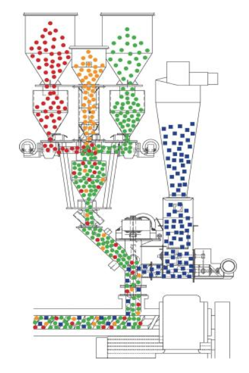
All materials are metered simultaneously directly into the extruder throat. (Drawing also shows film regrind being fed into the process.) Metering continues as long as the extruder is running.
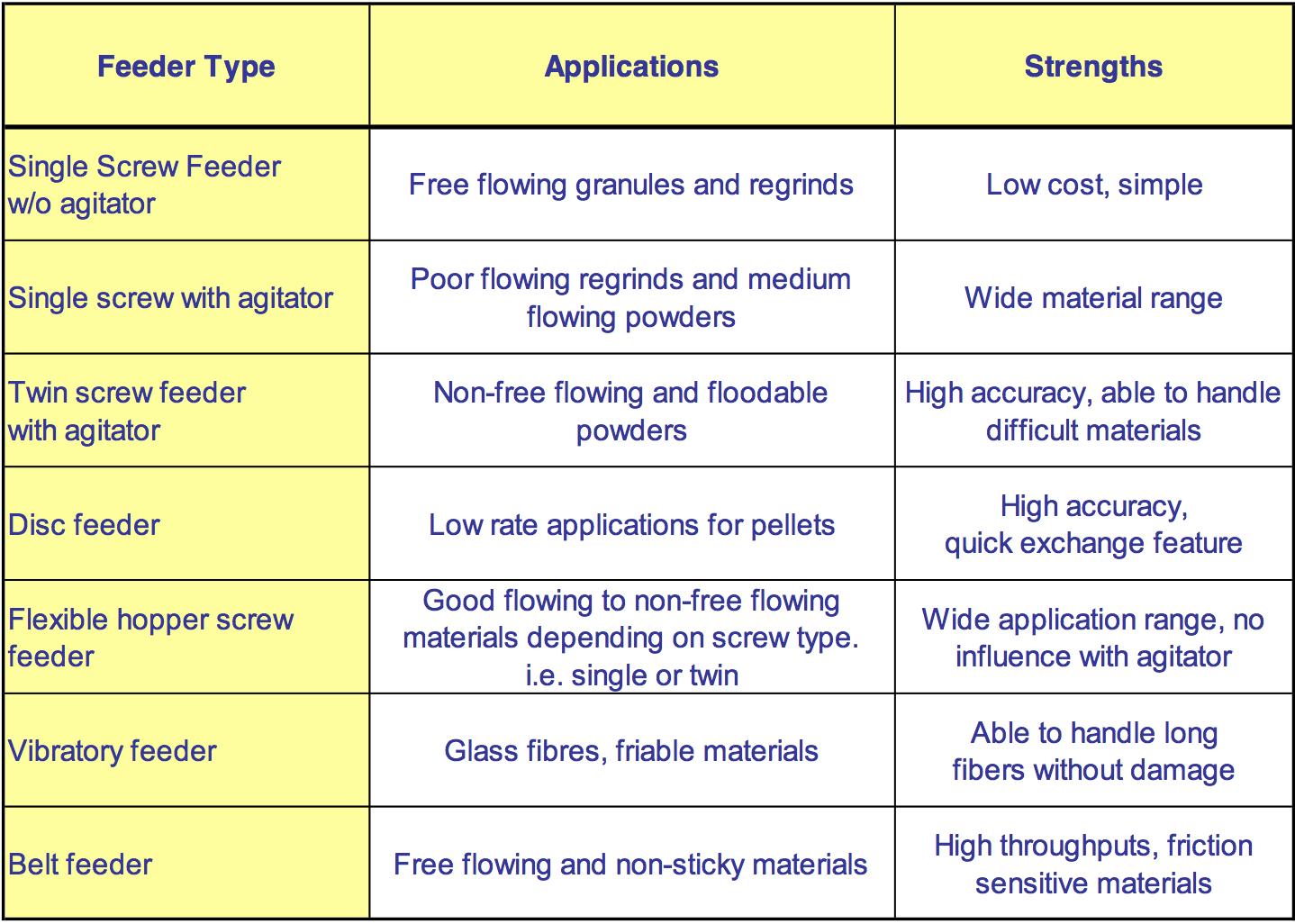
Feeders and Metering Devices
All of the systems described above can use a variety of metering devices to feed material into the gravimetric process, and each has its advantages. The most common are:
- Pneumatic slide gates – economical and reliable
- Augers, or screws – well known, but are inconsistent and inaccurate at low speeds
- Pinch valves – another twist on a slide gate, but a potential wear point
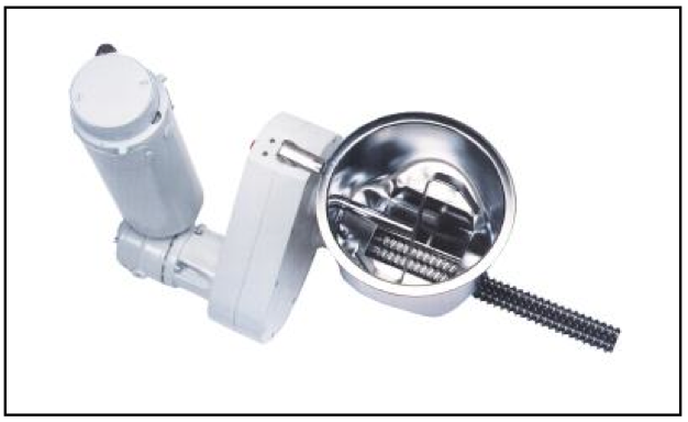
- Dosing disc – the most consistent feeder, especially at low rates (as low as 20 grams/hour)
- Vibratory feeder – works well with some materials
- Bulk solids pump – similar to a dosing disc feeder, but mounted vertically
- Rotary scalpel feeders – similar to a dosing disc feeder, but mounted vertically
Keep in mind that many materials are not free-flowing and will not feed consistently. Most gain-in-weight systems rely on controlled metering time to feed the given weight, and check the weight over time. If material does not feed consistently, which many don’t if you start and stop the flow every batch, the control system keeps adjusting the feed rate and can wind up chasing its tail. Continuous gravimetric systems keep the material moving all the time, and when used in conjunction with the proper agitation
Extrusion Control
Continuous loss-in-weight feeding can also be taken to the next level for even better process control. By connecting the starve feeder or extruder screw speed to the gravimetric hopper, material can be fed at a consistent, precise rate. You enter the rate you require and the extrusion control unit adjusts the screw speed to maintain that throughput.
You can also tie the unit into an encoder riding on your final product and control weight-per-length of the end product. Products with specific thicknesses, like tubing, pipe or sheet, can also use a gauging system tied to the extrusion control unit and maintain precise thickness of the final product. Versions of these systems are also used for gauging layer thickness in multi-layer products like film or sheet.
The benefits of this type of closed loop system are:
Improved process control
Improved product quality
Material savings through the reduction of over feeding
Inventory control
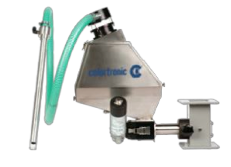
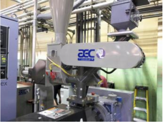
Film scrap reclaim
Film scrap can be recycled whether its edge trim scrap or defective rolls of film. The film re-feed systems can grind the scrap into “fluff” and re-feed it into the throat of your extruder in proportion to the pelletized material being extruded. These systems can re-feed the “fluff” up to 40% of the extruder output – some facilities are re-feeding at higher rates with certain materials.
In general, these systems can be used on any extruder that is not equipped with a grooved feed throat.
Communications
All of these systems can be connected to a data collection system that will allow the units to be controlled, and the data collected, from a central location, i.e. the plant manager’s office. Remote communication is available over Ethernet TCP/IP and Profibus networks, and most control systems feature internal diagnostics and user-friendly menu- based screens for easy operation. Wireless systems are also available, but have been problematic with all the electrical noise in a plant environment. These software packages are a very useful tool for consolidating control and reporting functions in a facility, or across multiple facilities.
Processors can save money, increasing the profitability of their operation, by:
Improving the feed accuracy to their extruders
Adding their own colorant and additives
Using their own regrind in the products they are manufacturing
Using post-consumer regrind (PCR) in the product by taking advantage of gravimetric control to achieve a more consistent product
In summary, many very good gravimetric blending systems are available to the processor today. Be sure to consider the types of material you are using, and what is important to your process. The key is selecting the system that is the most cost effective solution for your operation, but also the most modular one to accommodate your future needs!
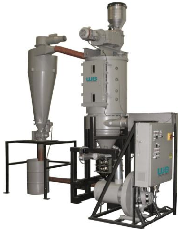
Crystallizing and drying systems
Some materials require crystallizing and/or drying to remove moisture prior to:
- Compounding
- Packaging of pellets for post-processing
- Processing into the final product
Non-hygroscopic materials require heated ambient air (typically 140o F to 180o F) to remove moisture, since the water is on the surface of the pellets and can be easily removed.
Other materials are hygroscopic, which means that moisture is absorbed inside the pellet. A dehumidifying dryer, supplying hot air at -40o F dew point, or lower, is required to extract the moisture from the material and eliminate the defects in the finished product. These materials are also usually dried at higher temperatures (typically 110o F to 350o F).
PET and PLA regrind must also be crystallized before it can be dried. Traditional systems use heated ambient air, while some new technology uses infrared energy to crystallize the regrind.
Size reduction systems
Most plastic processing facilities and all reclaim operations utilize some form of size reduction equipment.
Shredders are used to reduce large parts and purgings to smaller chunks (0.75 to 2 in.) that can be further reduced depending on the actual process.
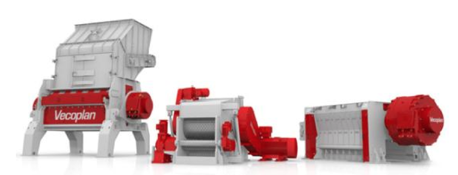
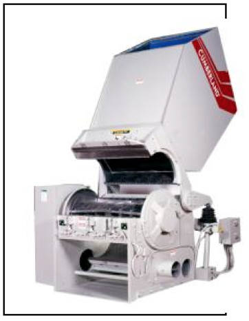
Granulators reduce the shredded material, as well as scrap product, into regrind (0.125 to 0.625 in.) that can be easily melted and re-used in the process machine.
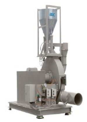
Pulverizers can be used to reduce certain virgin and regrind materials into powder (20 to 100 mesh) to ensure they are fully melted in the final process.
Crystallizing, drying and size reduction systems will be covered in other sessions and will not be detailed in this paper. They are only mentioned because they are an integral part of the entire material handling, process.
Conclusion
There are many opportunities available to improve the efficiency of your operation, and most equipment suppliers can help you exceed your specific requirements. With rising energy costs and tighter profit margins, everyone should be looking at ways to maximize the efficiency of their reclaim operations.
A properly designed feeding and blending system, in conjunction with the other peripheral equipment, is as important to the productivity of the plant as the extrusion technology itself. The analogy that “a chain is as strong as its weakest link” applies to reclaim extrusion as well. You don’t want a million dollar extrusion line sitting idle because you saved $5,000 when you bought your feeding system! You also don’t want to spend any more money than necessary to re-process your material, so an energy- efficient system should be in your future plans!
References
1. AEC/HydReclaim, Schaumburg, IL
2. Colortronic North America, New Berlin, WI
3. Cumberland, New Berlin, WI
4. K-Tron Systems, Pittman, NJ
5. Sterling Products, Inc., New Berlin, WI
6. Walton/Stout, New Berlin, WI
7. VECOPLAN LLC, Archdale, NC
Return to
Technical Papers.