Spalding Top Ten List ANTEC 2013
Troubleshooting Single-Screw Extrusion – Top 10 List
Mark A. Spalding, The Dow Chemical Company, Midland, MI
Gregory A. Campbell, Castle Research, Jonesport, ME
Goals
Provide a list of practices and skills
that every single-screw extrusion
engineer should know.
Top Ten List
1. Know how to calculate the expected rate for a single-screw extruder.
- Calculation of the rotational and pressure flows in the metering channel.
- The metering channel controls the rate.
- Calculation routines are available from SPE or you can easily construct a spreadsheet.
- Estimate the pressure profile.
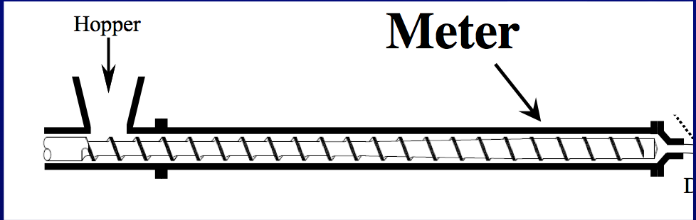
Figure 1. Campbell, G.A. and Spalding, M.A., “Analyzing and Troubleshooting Single-Screw Extruders,” Hanser Publications, Munich, 2013.
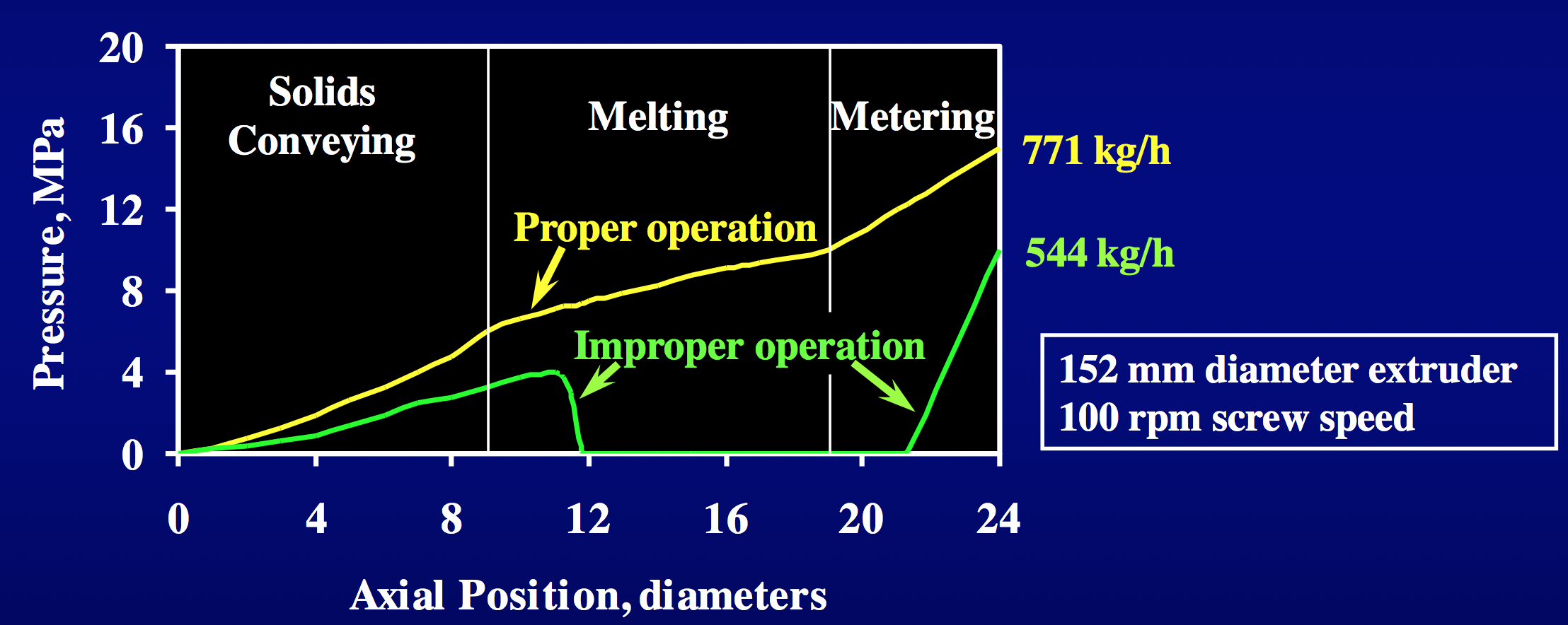
Figure 2.
2. Channels that are designed to operate full must be pressurized.
- Channels that are only partially filled operate at zero pressure.
- Partially filled channels create stagnation zones.
- Stagnation zones will cause some resin to degrade.
- Degradation products will eventually contaminate the final product.
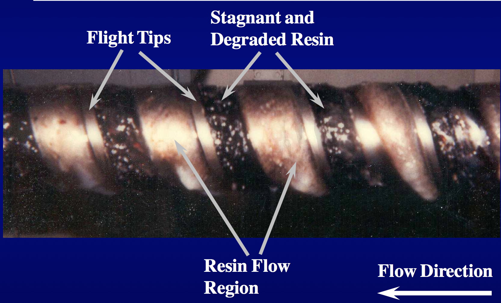

Figure 3-4. Hyun, K.S., Spalding, M.A., and Powers, J., "Elimination of a Restriction at the Entrance of Barrier Flighted Extruder Screw Sections," SPE-ANTEC Tech. Papers, 41, 293 (1995).
3. The flight radii should be between 0.5 and 2.5 times the channel depth.
- Small flight radii create a stagnant region between the flight edge and the screw root.
- The stagnant region will cause the resin to degrade and result in degradation products in the final product.
- The degradation at the flight radii were caused by low flow or stagnant regions due to Moffat eddies.
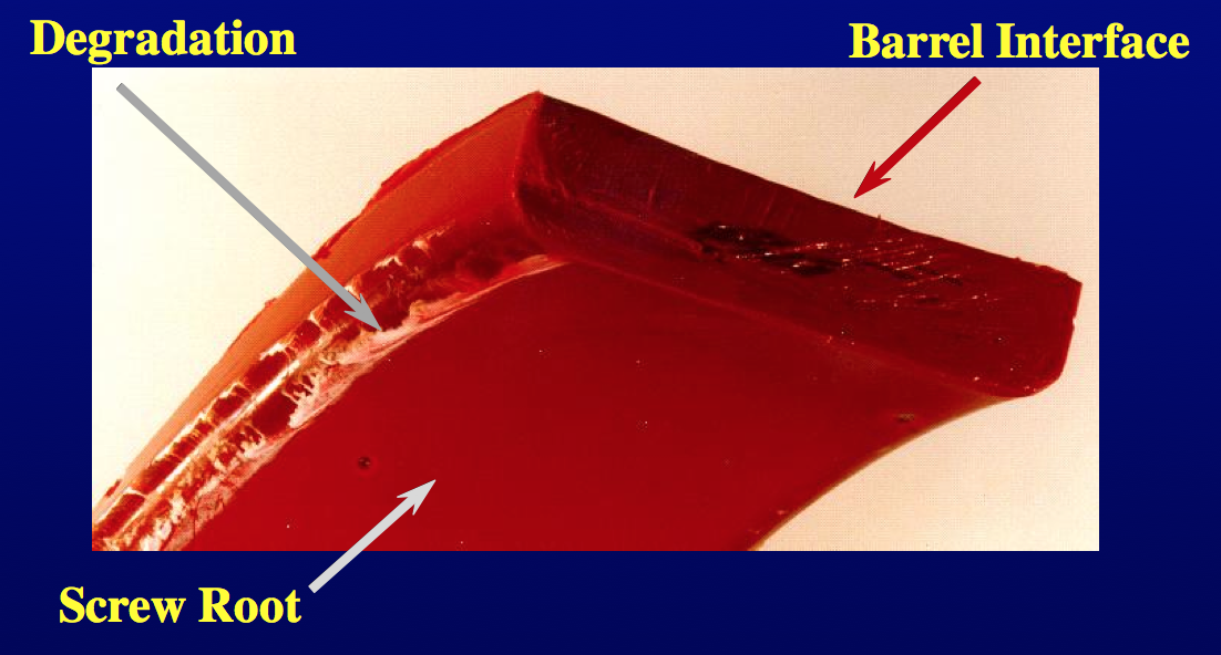
Figure 5.
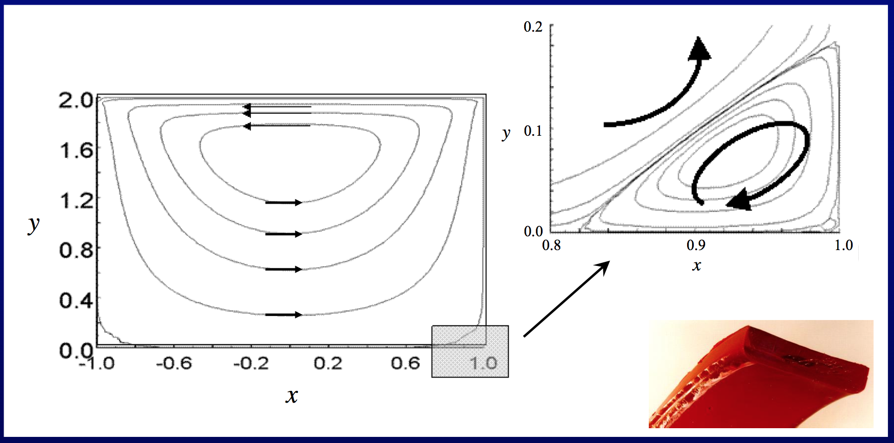
Figure 6.
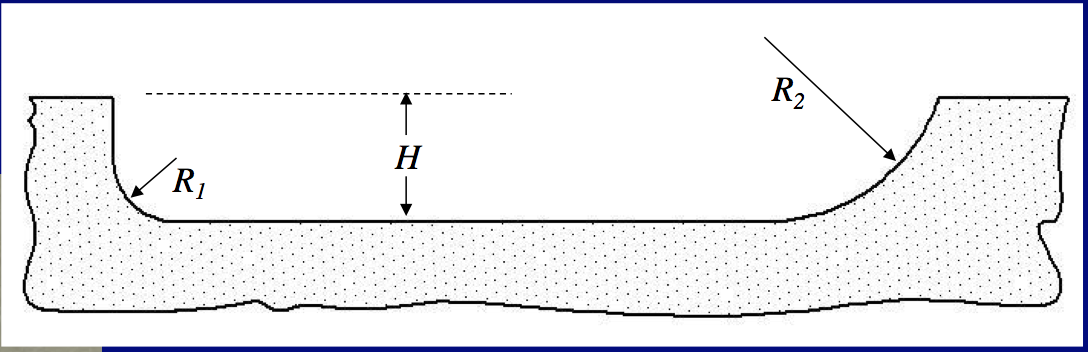
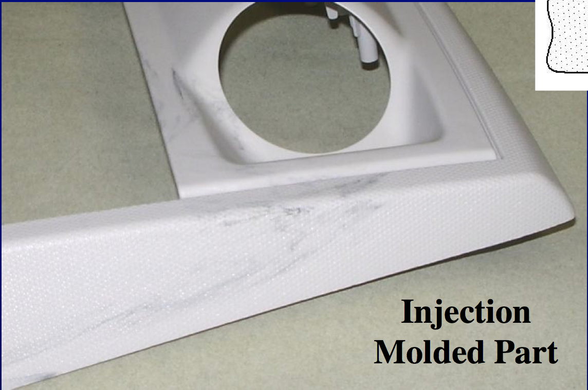
Figure 7-8. Flight radii design.

Equation 1.
4. Melting of the resin is the primary method for mixing.
- The best mixing occurs in the melt film between the solid bed and the barrel wall.
- The shear stress is very high in the melt film.
- A secondary mixing section is generally needed for most applications.
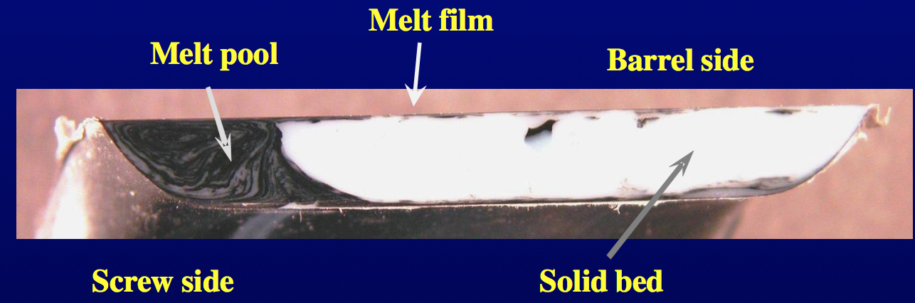
Figure 9.
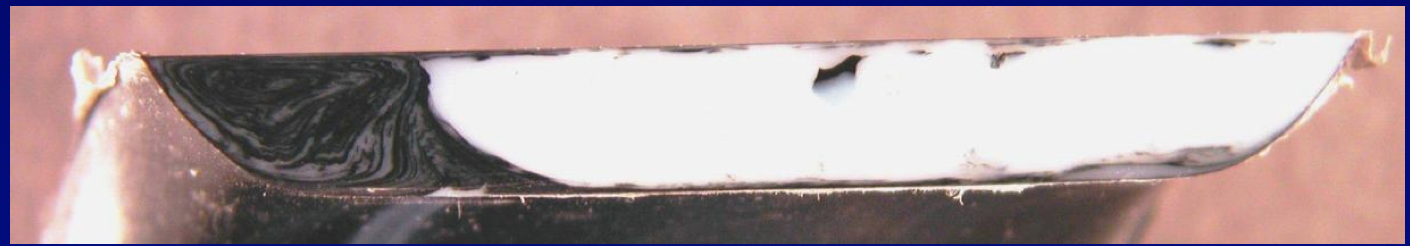
Figure 10. 100 parts white ABS to 1 part black ABS.
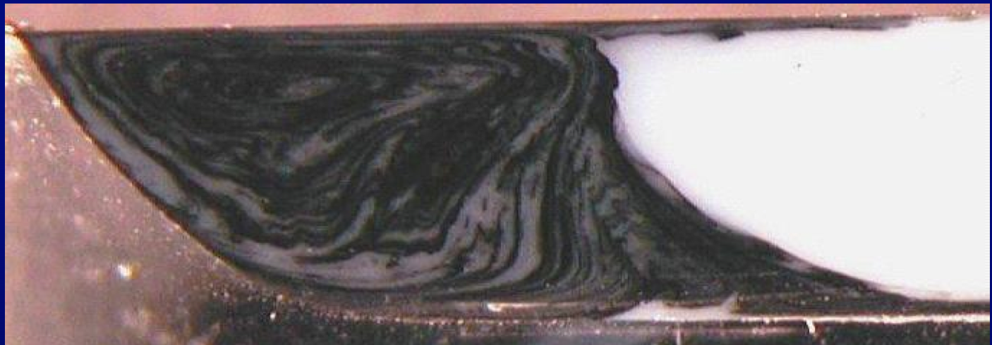
Figure 11. Single-flighted screw.
Benkreira, H., Shales, R.W., and Edwards, M.F., “Mixing on Melting in Single-Screw Extrusion,” Int. Polym. Process., 7, 126 (1992).
Campbell, G.A. and Spalding, M.A., “Analyzing and Troubleshooting Single-Screw Extruders,” Hanser Publications, Munich, 2013.
5. All screws will discharge solid resin if the screw is rotated fast enough.
- As a screw is rotated faster, a speed will be reached where solid resin is discharged with the extrudate.
- Solids in the extrudate can look like a poorly mixed system.
- A secondary mixer or a solids trap is needed for most applications.
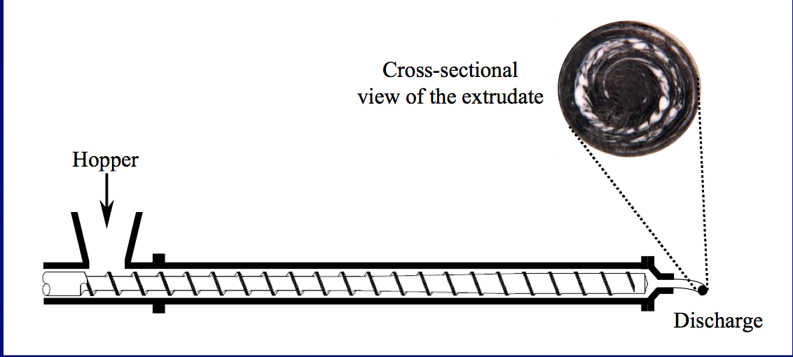
Figure 12. Extrude mixture with 99 parts white pellets with 1 part black pellets.
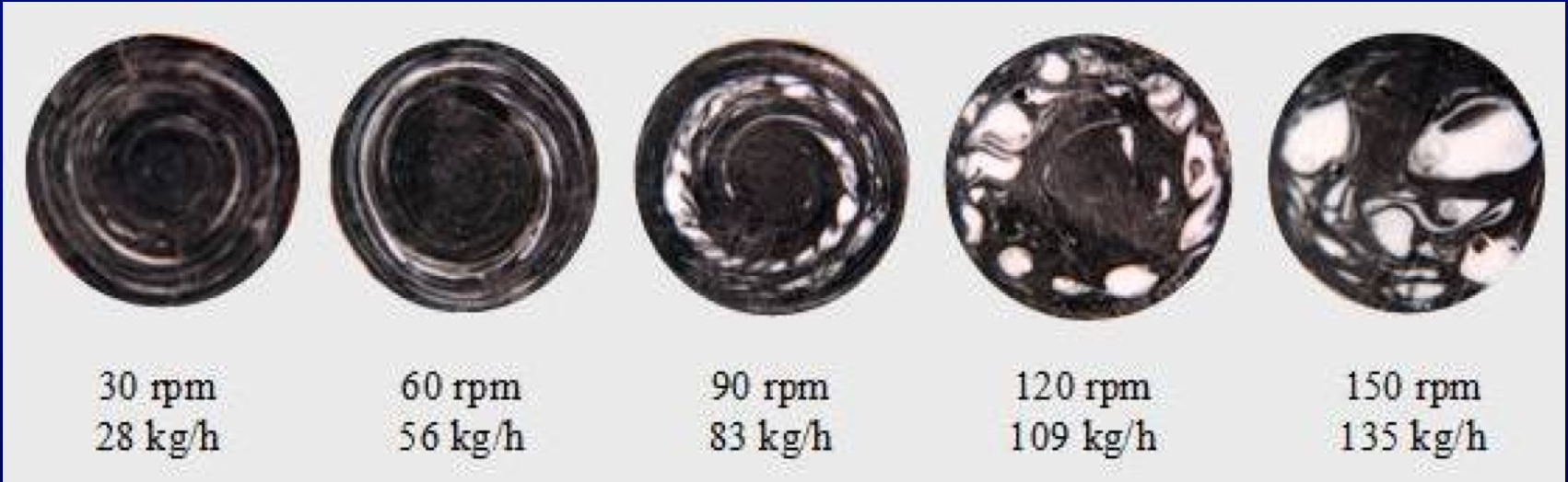
Figure 13. View extrudate sections.
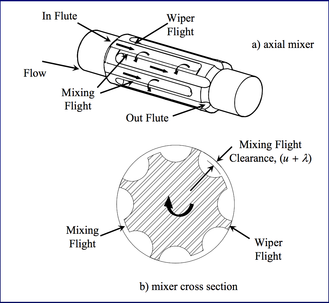
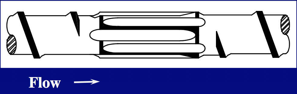
Figure 14-15. Maddock-style mixers are excellent secondary mixers for trapping and dispersing solid polymer fragments.
6. High-performance screws use specially designed channels to trap and melt solids.
- High-performance screws can operate at higher screw speeds, higher rates, and lower discharge temperatures as compared to a conventional screw with a mixer.
- High-performance screws have deeper metering channels.
- Several different types of high-performance screws are available.
- Common commercially available high-performance screws that employ this technology include: Wave screws, Energy Transfer (ET) screws, Fusion screws, DM2 screws.
- The Energy Transfer (ET) screw is constructed by positioning an ET section in the metering section of a conventional screw.
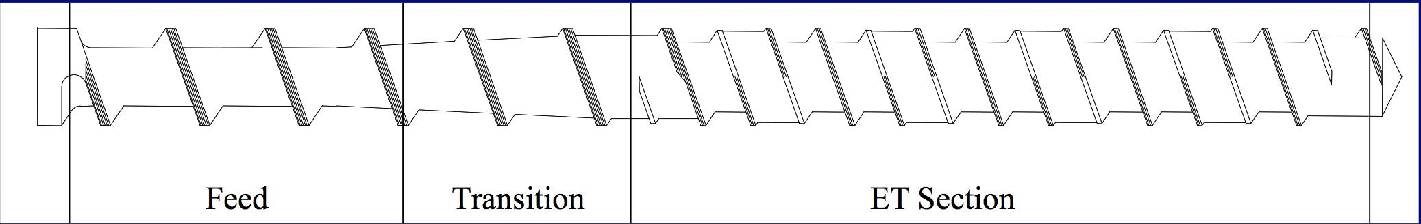
Figure 16.
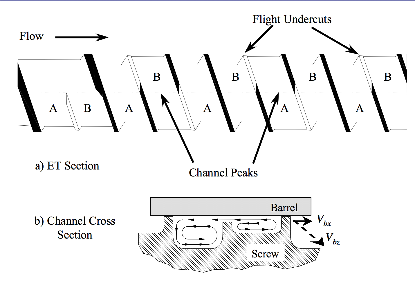
Figure 17.
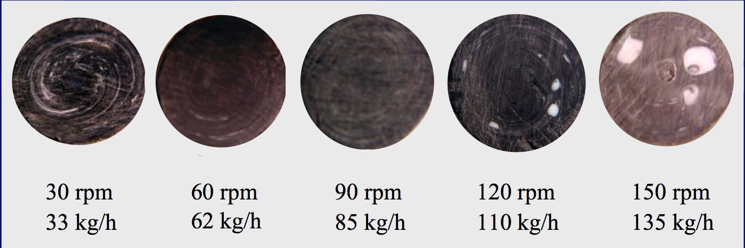
Figure 18. ET Screw
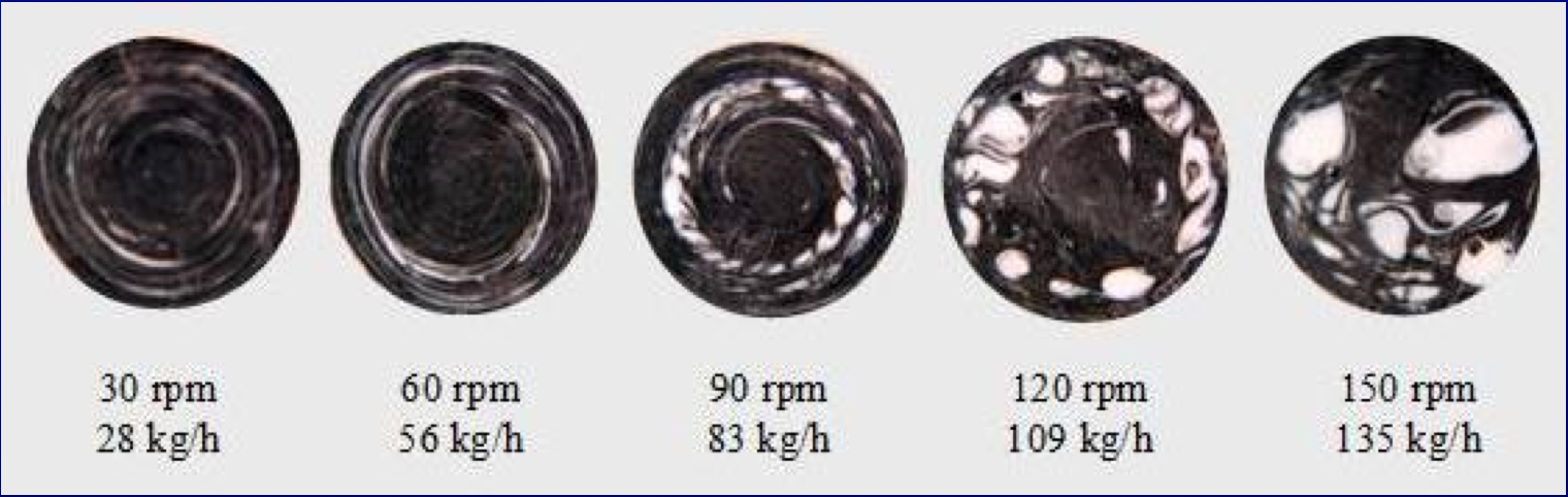
Figure 19. Conventional Screw
7. Injection molding screws use the same design principles as screws for extruders.
- All channels must operate full and under pressure.
- Operational rate is calculated using the mass of the parts and runner system, the plasticating time, and the screw speed.
- Rotational and pressure flow rates are calculated just like the procedure for extruders.
8. Flow surging is most often caused by a temperature control problem in the feed section.
- Proper solids conveying occurs with specific temperatures at the barrel wall and screw surfaces.
- Forwarding forces at the barrel wall must be maximized and the retarding forces at the screw must be minimized.
- Forces depend on temperature.
- Other root causes downstream of solids conveying are known to cause flow surging.
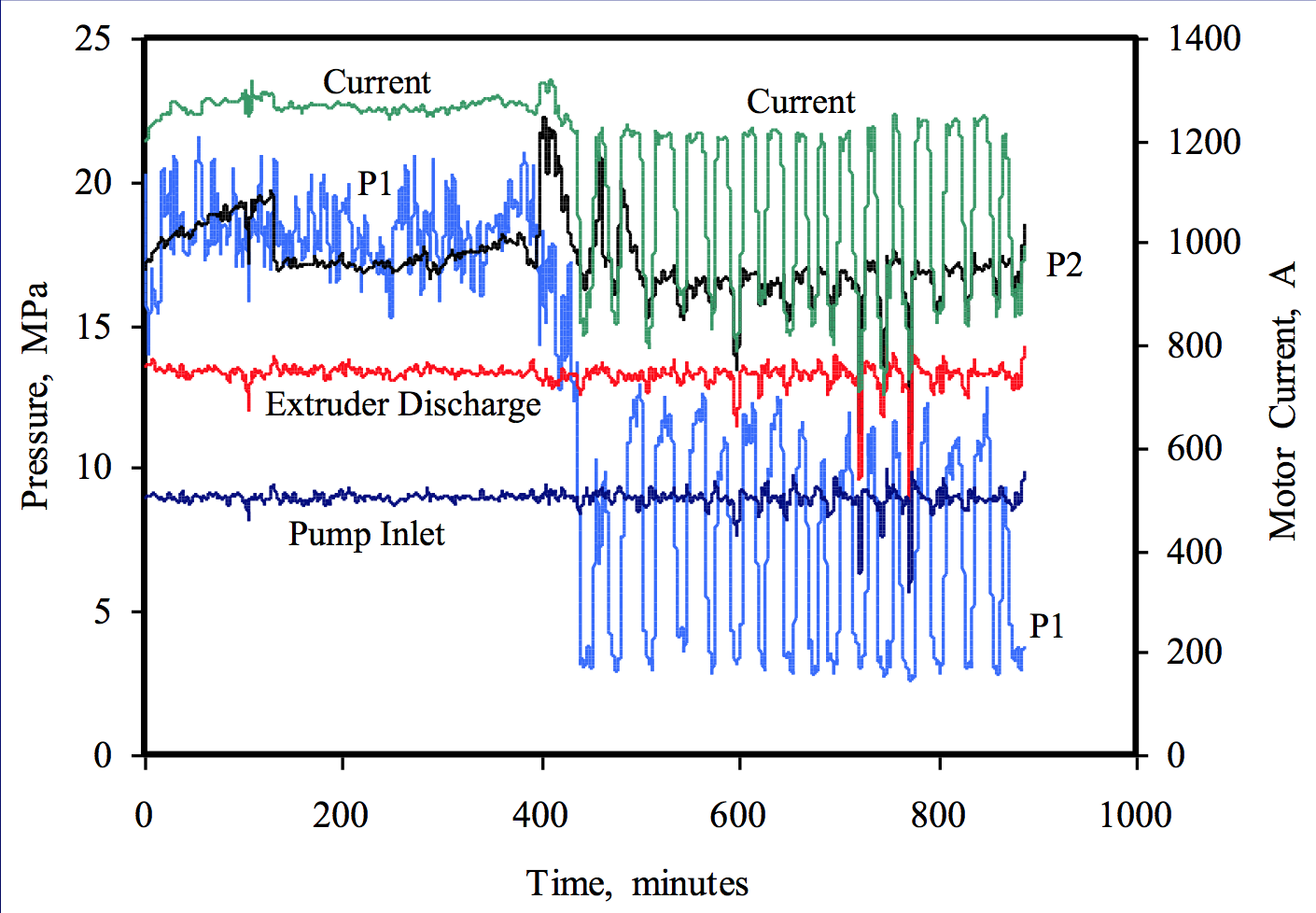
Figure 20. 203.2 mm diameter extruder. HIPS resin. Two-stage screw.
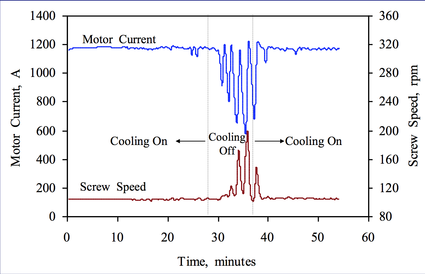
Figure 21. Instability was caused by a high temperature at the screw surface.
9. The first-stage metering section of a two-stage screw must control the rate.
- Two-stage extruders typically operate at a rate that is 1.1 to 1.3 times the rotational flow rate of the first-stage meter.
- A negative pressure profile exists in the first-stage meter.
- Vent flow will occur if the second stage limits rate.
- Vent flow can also occur if the vent diverter is not designed properly.
- A vent diverter is positioned in the vent opening to tuck molten resin back into the screw channel.
- If the diverter is not installed, installed improperly, or not designed properly, then flow of resin out the vent opening is likely.
Figure 22. Proper operation, no vent flow.
Figure 23. Proper operation, no vent flow. Vent Flow
Figure 24-25. Vent diverter
10. The first time a screw is installed into an extruder, both the screw and barrel should be at room temperature.
- If the screw has the correct outside diameter and it is not bent, then it should slide easily into the barrel.
- Never force a screw into a barrel.
- Never install for the first time a cold screw into a hot barrel – the hot barrel is oversize (thermal expansion) – the screw may slide in easily, but could expand to bind with the barrel.
Summary
- A list of ten top practices and skills were presented.
- Single-screw extrusion engineers should be aware of these practices and skills.
1. Hyun, K.S., Spalding, M.A., and Powers, J., "Elimination of a Restriction at the Entrance of Barrier
Flighted Extruder Screw Sections," SPE-ANTEC Tech. Papers, 41, 293 (1995).
2. Campbell, G.A. and Spalding, M.A., “Analyzing and Troubleshooting Single-Screw Extruders,”
Hanser Publications, Munich, 2013.
Return to
Paper of the Month.