Evaluation of 9-Layer Film Blowing Process by Using Variational Principles
Martin Zatloukal1,2, Roman Kolarik1
1 Centre of Polymer Systems, University Institute, Tomas Bata University in Zlin,
Nad Ovcirnou 3685, 760 01 Zlin, Czech Republic
2 Polymer Centre, Faculty of Technology, Tomas Bata University in Zlin,
TGM 275, 762 72 Zlin, Czech RepublicAbstract
In this work, coextrusion experiments utilizing an
industrial 9-layer Brampton Engineering coextrusion
film blowing line for LDPE/LDPE/tie/PA6/EVOH/PA6/
/tie/LDPE/LDPE film production has been performed
under different processing conditions (different air
cooling intensity and mass flow rate) in order to evaluate
variational principles based modeling approach for the
multi-layer film blowing process. It has been revealed
that the variational principle based model can describe
the bubble shape, temperature profile and predict internal
bubble pressure reasonably well for all applied
processing conditions even if the multi-layer film has
been viewed as the static elastic membrane characterized
only by one material parameter - bubble compliance J,
which was not allowed to vary along the multi-layer
bubble.
Introduction
Production of thin polymer films is mostly
introduced by the film blowing process. Although this
process is widely used, the single layer films do not
reach specific properties required especially in a food
packaging industry, such as barrier properties (low
permeability to oxygen or carbon dioxide), heat-seal
ability, high film strength, printability, adhesion and low
costs [1-2]. All these properties are easily and
economically achievable in multi-layer films produced
by coextrusion.
In coextrusion, two or more different polymer melts
(having various rheological properties and temperatures)
are extruded from individual extruders, through a
coextrusion die, to a continuous tube which is cooled by
an air ring and internal bubble cooling system, IBC,
axially stretched by the take-up force, F, and
circumferentially inflated by the internal bubble
pressure, Δp, to required bubble dimensions. Then,
above the freezeline height, the stable solidified bubble
is folded by the collapsing frames and consequently
drawn upward by the nip rolls to a wind-up roll. Then,
the final lay-flat coextruded multi-layer film, which
represents a combination of the best properties of each
used polymers, can be applied for example in food
packaging, medical and electronic industry. The most
frequently used materials in coextrusion are polar barrier
polymers, such as nylon (PA), ethylene vinyl alcohol
(EVOH), polyvinylidene chloride (PVDC), and nonpolar
polyolefines, i.e. polyethylene (PE), polypropylene
(PP), polystyrene (PS) [1-2].
In spite of a rapid growth of a blown film coextrusion
in the last decades, the number of experimental and
modeling studies of the multi-layer process is very
limited. In 1978, Han and Shetty [3] experimentally and
theoretically investigated blown film coextrusion of two
polymers in various combinations, i.e. low density
polyethylene (LDPE) with ethylene-vinyl acetate (EVA),
LDPE with high density polyethylene (HDPE), LDPE
with polypropylene (PP) and HDPE with EVA. Further,
they performed a theoretical study where the experiment
was theoretically analyzed by using a power-law nonNewtonian
model included in a computational procedure
predicting the number of layers, layer thickness and the
volumetric flow rate compared with the experiment.
Theoretical investigation of two-layer coextruded blown
film was also studied by Yoon and Park [4] in 1992. In
their work, considering isothermal processing
conditions, two film layers are described by a Newtonian
and an Upper-Convected Maxwell fluid (UCM). In order
to evaluate influence of viscous and viscoelastic forces
on the flow mechanics of the process, the various flow
rate ratio values of the fluids are applied for numerical
determination of the bubble radius and the film thickness
profiles. It was revealed, that in the case of the small
relaxation time the flow mechanics of UCM layer is
similar to a Newtonian single-layer. On the other hand,
increasing relaxation time supports the viscoelasticity
effect of the UCM layer leading to dominance of bubble
dynamics. In 2000, Yoon and Park [5] performed a
linear stability analysis of the above presented polymer
system. It was observed that the critical film thickness
decreases with increasing blow-up ratio which makes the
process unstable. In more detail, in case of a Newtonian
single-layer flow, there exists an upper unstable region where the bubble is unstable when the BUR is greater
than a certain critical value. On the other hand by the
presence of a thin viscoelastic layer this restriction can
be removed resulting in enhanced stable area at higher
values of BUR. In 2000, Stasiek [6] studied the heat
transfer between three-layer blown film and cooling
medium. In his work, mathematical model, estimating
length of a cooling path and taking into account
crystallization effect, was developed and used to
describe the relationship between the temperature
changes in each layer and the thermal energy. In 2005,
Elkoun et al. [7] investigated effect of composition and
layout of layers on end-use properties of a coextruded
LLDPE five-layer blown film. For coextruded structure,
a conventional Ziegler-Natta LLDPE gas phase butene
copolymer, an advanced Ziegler-Natta LLDPE solution
octene copolymer, and a single site LLDPE solution
octene copolymer were used and compared with monolayer
blended film. It was observed, that combination of
the LLDPE butene and the single site LLDPE in a fivelayer
coextruded film reveals improved tear resistance
due to a presence of interfacial transcrystalline layers.
Further, combination of coextruded single site LLDPE
and the Ziegler-Natta octane copolymers leads to
enhanced tear strength, too. Finally, significant haze
reduction, caused by placing the single site LLDPE on
the outside layers of the multi-layer films, was observed.
In 2005, Gamache et al. [8] performed experimental and
theoretical study evaluating stresses in a two-layer
coextruded blown film of LDPE, ultra low density
polyethylene (ULDPE), LDPE/ULDPE and
ULDPE/LDPE. Then, the axial and transverse stresses
were experimentally measured under various processing
conditions, which were then successfully compared with
theoretically calculated ones by the non-isothermal
Newtonian model. In 2007, Gururajan and Ogale [9]
studied effect of coextrusion on the orientation and
morphology of the coextruded films of PP and LDPE by
using Raman spectroscopy. In the case of multi-layer
films, no significant difference in overall molecular
orientation of PP and LDPE was found. On the other
hand, single-layer LDPE films indicated existence of
some row-nucleation of crystals which was not observed
in the LDPE layer in coextruded film. In 2009, a 2-D
model describing non-isothermal two-layer blown film
process was developed by Xu and McHugh [10]. This
model is based on the 1-D model of Henrichsen and
McHugh [11] taking to account viscoelasticity and flowenhanced
crystallinity. The 2-D model presents
numerical results showing influence of the rheological,
thermal and crystallization properties on the crystallinity
development and stresses in particular layers. It was
observed, that the individual layers of the same materials
contain significantly different stresses due to the
temperature difference. Further, different material
properties in a certain layer affect stresses and
crystallinity in its own layer as well as in another layer
through heat transfer. Finally, stresses and semicrystalline
phase orientation at the freezeline, i.e. final
film properties, are affected by the layer arrangement.
As can be seen from the literature overview, the
number of theoretical studies of the multi-layer film
blowing process is rather rare, considering maximally 3
layers and laboratorial processing conditions only due to
extremely high mathematical and rheological complexity
of the problem. Due to this, the multi-layer film blowing
process for high number of layers and industrial
processing conditions is not fully understood yet.
Recently, it has been found that utilization of the
variational principle based single-layer film blowing
process modeling leads to very stable numerical schemes
allowing qualitative as well as quantitative description of
the experimental reality [12-18]. The main goal of this
work is to investigate whether it is possible to utilize the
variational principles based modeling approach for the
multi-layer film blowing process. For the model
validation purposes, industrial 9 layer film blowing line
has been utilized to produce multi-layer bubbles under
different processing conditions.
Mathematical Modeling
Zatloukal-Vlcek Formulation
The variational principle based Zatloukal-Vlcek
formulation [12] describes a stable film blowing process
as a state when the bubble shape satisfies minimum
energy requirements (here the bubble energy is given by
the elastic strain energy increase due to take up force and
negative work done by the applied internal load). The
bubble shape is described by a set of simple analytical
equations (see Table 1) utilizing four physical
parameters: the freezeline height, L, the bubble
curvature, pJ (which is given by the membrane
compliance, J, and the internal load, p, representing the
internal force acting on the bubble length due to Δp – see
Eq. 6), the inner die radius, R
0 and the blow-up ratio,
BUR. It should be mentioned that the equations
describing the freezeline height (Eq. (7)) and the
temperature profile (Eq. (8)) have been derived in [13]
from the cross-sectionally averaged energy equation [19]
neglecting axial conduction, dissipation, radiation effects
and crystallization. The particular symbols with respect
to model equations summarized in Table 1 have the
following meaning: C
p represents the specific heat
capacity, HTC is the heat transfer coefficient, m is the
mass flow rate, T
melt(die) represent the die exit melt
temperature, T
solid is the solidification temperature and
T
air is the cooling air temperature. Parameter φ is defined
according to Table 2 where a parameter A is defined by
Eq. (4).
Experimental
In this work, coextrusion experiments were carried
out on an industrial 9-layer Brampton Engineering
coextrusion film blowing line (Figure 1) equipped with a
350 mm diameter flat spiral die (R0 = 0.1626 m) with a
die gap of 2.032 mm (H0 = 0.002032 m). During the
process, the bubble was cooled by an air ring as well as
by an internal bubble cooling system. The coextruded
structure was LDPE/LDPE/tie/PA6/EVOH/PA6/tie/
/LDPE/LDPE with following layer thicknesses: 17.5 %
for LDPE, 5% for tie, 5% for PA6 and 10% for EVOH.
In all experiments, the following parameters were kept to
be constant: die exit temperature, Tdie = 250°C, overall
film thickness (gauge), H1=100 μm, (which corresponds
to draw-down ratio DDR = 11.17), blow-up ratio, BUR =
1.8, and lay-flat film, 1000 mm. During the experimental
work, firstly, different bubble cooling intensity was
applied at the constant overall mass flow rate, 300 kg/h,
(i.e. constant line speed 25.9 m/min) and secondly,
overall mass flow rate was varied from 225 kg/h to 375
kg/h (i.e. from 19.4 m/min to 32.3 m/min for the line
speed) by keeping the bubble cooling intensity the same.
For given processing conditions, the bubble shape
was monitored by the EOS digital SLR photo camera
Canon EOS 450D model (Canon, Inc., Japan) with
resolution of 12.2 Mpx equipped with Canon lens EF-S
18-55mm f/3.5-5.6 IS whereas the average bubble
temperature was measured by the heat gun, model
camera: INFRACAM
TM using calibration site FLIR
SYSTEM, AB SWEDEN and corresponding software
(ThermaCAM QuickReport 1.0).
Results and Discussion
At the beginning, three unknown film blowing model
parameters L, BUR and pJ (for the known die radius
R0 = 0.1626 m) were determined through fitting of all
experimentally obtained bubble shapes by Eq. (8)
utilizing the least square minimization method and they
are summarized in Table 3. In order to calculate the takeup
force and the internal bubble pressure for given
processing conditions, p and J parameters were separated
from the particular pJ value in the same way as
described in [12] i.e. parameter J (which is viewed as
constant characterizing the bubble compliance) was
determined from pJ value for one reference processing
conditions for which the load p was chosen to get equal
predicted and measured internal bubble pressure. The
reference processing conditions are provided in the
second column of Table 3.
The comparison between the experimentally
determined bubble shape and internal bubble pressure
for all tested processing conditions are summarized in
Figures 2-3 and Table 3, respectively, and as it can be
seen, the agreement between the measured data and
model fits/predictions is very good. In more detail, the
model can describe the bubble shape as well as
temperature profile along the bubble and predict internal
bubble pressure reasonably well for both, decreased
freeze line height and the bubble curvature due to
increased air cooling intensity or decreased mass flow
rate under highly non-isothermal conditions, even if the
assumption about the constant bubble compliance J
along the multi-layer bubble has been used. The fact that
the single parameter J works could be explained by the
statement that the layers which freezes first in
coextrusion dictates the bubble shape [20-21]. This
suggests, that the variational principle based modeling
approach proposed in [12] can be used and explored for
the multi-layer film blowing process in the similar way
as shown in [12] for single-layer film blowing process.
Moreover, it is believed, that such theoretical approach
can be used to understand complex heat transfer and
crystallization effects occurring in multi-layer film
blowing process resulting in highly non-linear average
temperature profile along the multi-layer bubble,
depicted in Figures 2c and 3c for the studied
experimental conditions, which is not the case of the
single-layer film blowing process at which the average
temperature profile along the bubble is almost linear as
shown in [22-29].
Conclusion
In this work, coextrusion experiments utilizing an
industrial 9-layer Brampton Engineering coextrusion
film blowing line for
LDPE/LDPE/tie/PA6/EVOH/PA6/tie/ /LDPE/LDPE film
production has been performed under different
processing conditions (different air cooling intensity and
mass flow rate) in order to evaluate variational principles
based modeling approach for the multi-layer film
blowing process.
It has been revealed that the variational principle
based model can describe the bubble shape, temperature
profile and predict internal bubble pressure reasonably
well for both, decreased freeze line height and the bubble
curvature due to increased air cooling intensity or
decreased mass flow rate under highly non-isothermal
conditions even if the multi-layer film has been viewed
as the static elastic membrane characterized only by one
material parameter - bubble compliance J, which was not
allow to vary along the bubble. Thus, it is believed, that
the variational principle based modeling approach can be
used and explored for the multi-layer film blowing
process to understand complex rheological, heat transfer
and crystallization phenomena occurring in multi-layer
film blowing process with respect to process stability
and final film properties.
Acknowledgments
The authors wish to acknowledge the Grant Agency
of the Czech Republic (grant No. P108/10/1325) for the
financial support. This article was written with support
of Operational Program Research and Development for
Innovations co-funded by the European Regional
Development Fund (ERDF) and national budget of
Czech Republic, within the framework of project Centre
of Polymer Systems (reg. number:
CZ.1.05/2.1.00/03.0111).
The authors would also like to thank Brampton
Engineering Inc. which allowed us to perform all
experimental work on their complete commercial size 9-
layer AeroFrost air cooled blown film line.
References
1. Cantor, K. Blown Film Extrusion. Munich: Carl
Hanser Verlag, 2006. ISBN 3-446-22741-5.
2. Butler, T.I. Film Extrusion Manual: Process,
Materials, Properties. Atlanta: Tappi Press, 2005.
ISBN 1-59510-075-X.
3. Han, C.D., Shetty, R., Polym. Eng. Sci. 1978, vol.
18, no. 3, pp. 187-199.
4. Yoon, K.S., Park, C.W., Polym. Eng. Sci. 1992,
vol. 32, no. 23, pp. 1771-1777.
5. Yoon, K.S., Park, C.W., J. Non-Newtonian Fluid
Mech. 2000, vol. 89, no.1-2, pp. 97-116.
6. Stasiek, J., Prog. Rubber Plast. Recycl. Technol.
2000, vol. 16, no. 3, pp. 183-192.
7. Elkoun, S., Huneault, M.A., McCormick, K.,
Puterbaugh, F., Kale, L., Polym. Eng. Sci. 2005,
vol. 45, no. 9, pp. 1222-1230.
8. Gamache, E., Agassant, J.F., Demay, Y., Lafleur,
P.G., J. Plast. Film Sheeting 2005, vol. 21, no. 2,
pp. 127-144.
9. Gururajan, G., Ogale, A.A., J. Plast. Film Sheeting
2007, vol. 23, no. 1, pp. 37-49.
10. Xu, F., McHugh, A.J., Chem. Eng. Sci. 2009, vol.
64, no. 22, pp. 4787-4795.
11. Henrichsen, L.K., McHugh, A.J., Int. Polym. Proc.
2007, vol. 22, no. 2, pp. 179–189.
12. Zatloukal, M., Vlcek, J., J. Non-Newton. Fluid
Mech. 2004, vol. 123, no. 2-3, pp. 201-213.
13. Kolarik, R., Zatloukal, M., J. Appl. Polym. Sci.
2011, vol. 122, no. 4, pp. 2807-2820.
14. Kolarik, R., Zatloukal, M., AIP Conference
Proceedings 2009, vol. 1152, pp. 251-269.
15. Zatloukal, M., Kolarik, R., Annual Technical
Conference - ANTEC, Conference Proceedings
2009, vol. 3, pp. 1587-1595.
16. Zatloukal, M., Kolarik, R., Annual Technical
Conference - ANTEC, Conference Proceedings
2011, vol. 2, pp. 1317-1322.
17. Kolarik, R., Zatloukal, M., AIP Conference
Proceedings 2011, vol. 1375, pp. 56-74.
18. Kolarik, R., Zatloukal, M., Martyn, M.,
International Journal of Heat and Mass Transfer
2013, vol. 56, no. 1, pp. 694-708.
19. Doufas, A.K., McHugh, A.J, J. Rheol. 2001, vol.
45, no. 5, pp. 1085-1104.
20. Morris, B.A., Journal of Plastic Film and Sheeting,
1999, 15(1), 25-36.
21. Giriprasath, G., Ogale, A.A., Annual Technical
Conference – ANTEC, Conference Proceedings,
2006, 2, 830-834.
22. Wagner, M.H., Ph.D. Thesis, IKT Stuttgart, 1976.
23. Fisher, E., Ph.D. Thesis, IKT Stuttgart, 1983.
24. Cao, B., Sweeney, P., Campbell, G.A., J. Plast.
Film Sheeting 1990, vol. 6, no. 2, pp. 117-130.
25. Kanai, T., White, J.L., Polym. Eng. Sci. 1984, vol.
24, no. 15, pp. 1185-1201.
26. Ast, W., Ph.D. Thesis, IKT Stuttgart, 1976.
27. Muslet, I.A., Kamal, M.R., J. Rheol. 2004, vol. 48,
no. 3, pp. 525-550.
28. Beaulne, M., Mitsoulis, E., J. Appl. Polym. Sci.
2007, vol. 105, no. 4, pp. 2098-2112.
29. Sarafrazi, S. Sharif, F., Int. Polym. Proc. 2008, vol.
23, no. 1, pp. 30-37.
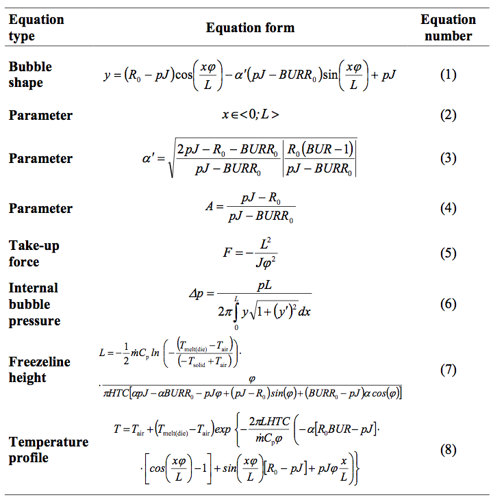
Table 1. Summary of the Zatloukal-Vlcek film blowing model equations [12-13].
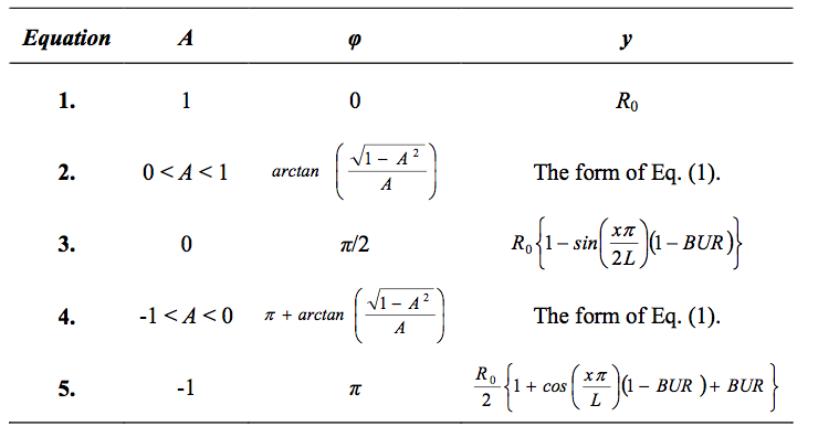
Table 2. Parameters A and φ for different bubble shapes (y) [12].
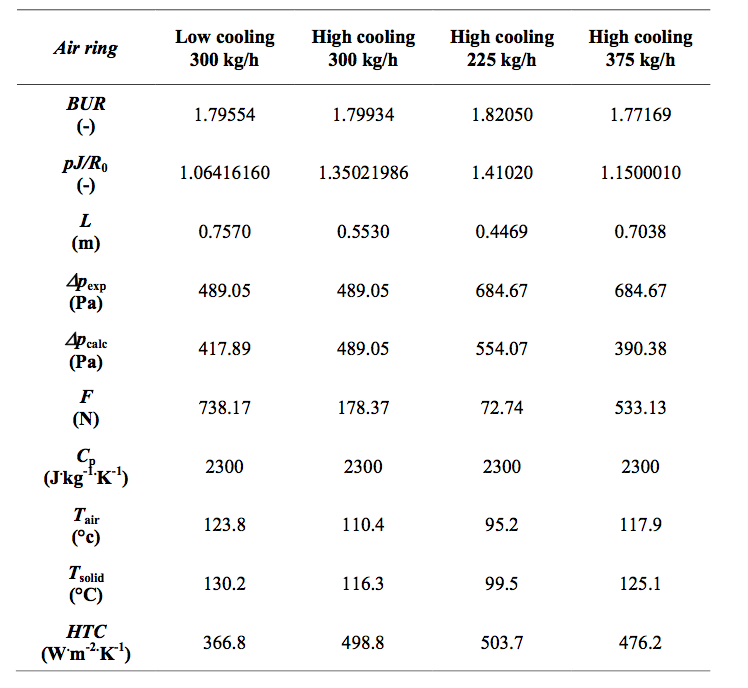
Table 3. Summarization of the model parameters and model predictions (by keeping the bubble compliance J the same for all the cases equal to 0.00028221 Pa-1) for all tested processing conditions including the measured value of the internal bubble pressure Δpe
xp.

Figure 1. Brampton Engineering 9-layer air cooled blown film line. 1a) Side view. 1b) Detail view of the 9-layer film formation at multi-layer die exit region including the scale for precise bubble shape determination by using digital image analysis.
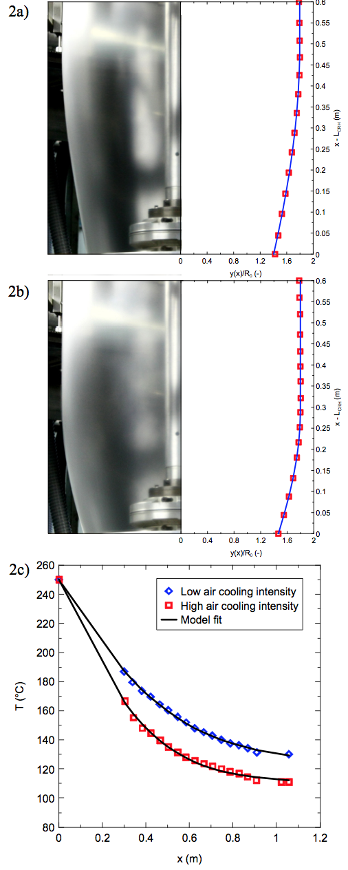
Figure 2. Comparison between experimentally determined multi-layer bubble shape and temperature profile (open symbols) and model fits (lines) for different air cooling intensity and fixed mass flow rate equal to 300 kg/h (cooling ring height, LCRH = 0.26 m). 2a) Bubble shape for low air cooling intensity. 2b) Bubble shape for high air cooling intensity. 2c) Temperature profiles for both applied air cooling intensities.
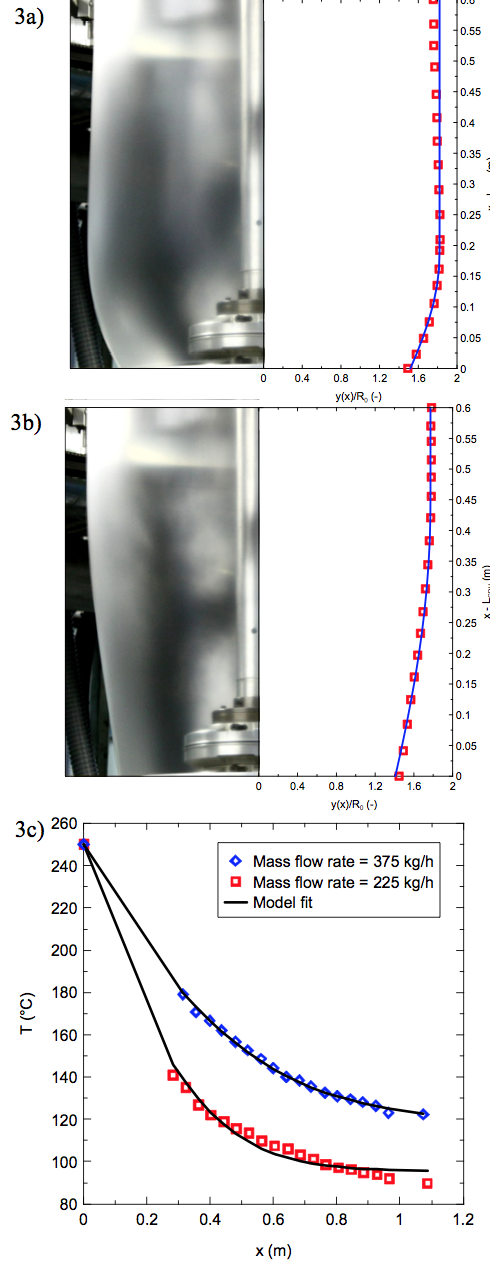
Figure 3. Comparison between experimentally determined multi-layer bubble shape and temperature profile (open symbols) and model fits (lines) for different mass flow rates and fixed air cooling intensity (cooling ring height, LCRH = 0.26 m). 3a) Bubble shape for mass flow rate equal to 225 kg/h. 3b) Bubble shape for mass flow rate equal to 375 kg/h. 3c) Temperature profiles for both applied mass flow rates.
Return to
Paper of the Month.