Modeling of Anisotropic Polymers during Extrusion
Arash Ahmadzadegan, Michael A. Zimmerman, Anil Saigal
Department of Mechanical Engineering
Tufts University
Medford, MA 02155 Abstract
It is known that a liquid crystal polymer (LCP) melt
aligns in the direction of the shear flow when it passes
through an extrusion die. This alignment causes thin films
of the anisotropic LCP material to display different
properties in different directions. To overcome this
problem, many complex die design technologies have
been developed that involve moving surfaces. However,
there is a clear need to develop a method of predicting
crystal orientation (alignment) to aid in die design. This
paper investigates different modeling methods, and
develops a numerical modeling technique using FLUENT,
to predict molecular alignment by correlating it to
streamlines of flow. This model also incorporates the
complex rheology of the LCP in predicting the resulting
alignment. It is shown that for a new cross-flow design of
the extrusion die that at around Re=500 the maximum
angle between the vectors is 80 degrees and at lower Re it
does not satisfy the desired angle between the two flows.
Introduction
Any rod like molecule or crystal tends to orient itself
in the direction of shear as it moves with in a flow. Since
polymers consist of long chains of molecules, they
experience the same phenomena when flowing in the melt
condition. For most polymers, the molecules change
direction and distribute uniformly in space during the
solidification. However due to the higher inertia of the
crystals in the liquid crystalline polymers, the oriented
crystals will keep their order during the solidification and
as a result the final product will show anisotropy in the
material properties.
This investigation focuses on film casting of LCPs
and develops ways to prevent the anisotropy of properties
in the final product. The challenge here is to alter the
rheology of the polymer melt inside the die in order to
have isotropic material properties in the plane of the film.
The use of biaxial shear flow during extrusion,
elongational strain after extrusion, electromagnetic field
effects, and thermal treatment to develop isotropic films
has been discussed by Lusignea et al. [1].
Farrell and Lawrence use co-rotating extrusion dies to
produce biaxially oriented films of LCPs [2]. Due to the
complexity of this type of dies and built-in instabilities
during this extrusion process, a simpler stationary
extrusion die is desirable.
Geometry
An important parameter to be considered when
designing the geometry of polymer dies is that the flow
pattern inside the die highly influences the polymer
extrusion process and any sharp edges inside the die which
result in the flow to become turbulent should be avoided
[3]. Turbulence inside the die increases the residual
stresses which will be released after the extrudate leaves
the die and causes instabilities in the extrusion process.
The conventional die for extrusion of polymer films or the
coat-hanger design is shown in Figure 1. These dies are
designed such that the velocity of the extrudate coming
out of the die is constant across the lip of the die.
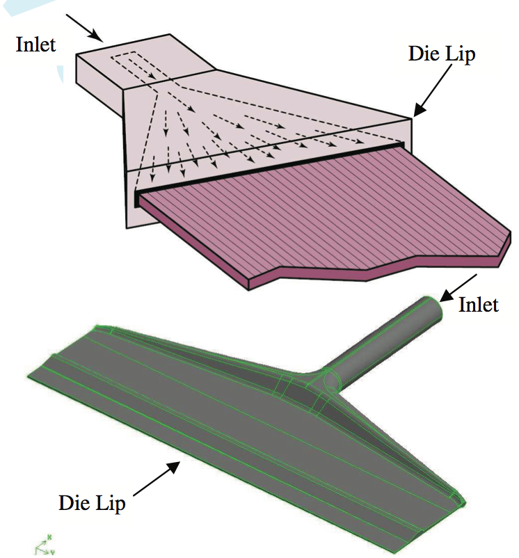
Figure 1. Schematic of a coat-hanger die (up) inside the actual die (down) [4]
In this study, simulation of the polymer flow inside
this die geometry was performed with different material
properties to investigate the difference between the
rheology and the dependence of pressure drop on the
material properties. Another type of dies which is
designed to produce plane isotropic properties is corotating
extrusion die. The co-rotating extrusion dies try to
use the viscosity of the polymer to produce a laminar flow
with a lateral shear flow that has a three dimensional
profile at the lip of the die. This geometry, as shown in
Figure 2, has two co-rotating cylinder which operate at
high temperature and the polymer melt flows between
them. The change in the direction of the crystallines is
introduced through the shear effect of the cylinders.
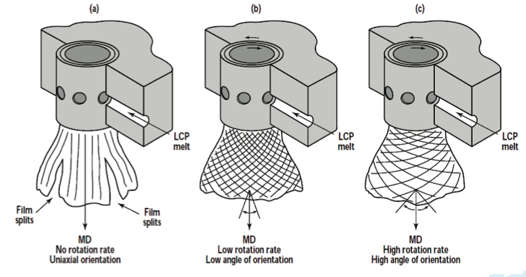
Figure 2. Geometry of the co-rotating biaxial die [4]
A new design for the die geometry introduced here
uses cross flows to produce the required lateral shear
across the thickness of the film. As a result, no moving
part is used in the die. A simple geometry of cross-flow
die consists of two cross flows which interact with each
other along the mid-plane. The interaction of these two
symmetrically positioned flows causes the mid-plane to
exit the lip normal to the exit plane while from the midplane
to the upper and lower planes velocity vectors
change direction gradually. To construct this geometry,
preprocessing software GAMBIT was used since it can
export the geometry, mesh and boundary conditions to
FLUENT. The idea of interacting cross flows was built
with 20 channels in which the flow in half of them is
perpendicular to the other half. These channels are open
along the interface between them and provide the
interaction of flows inside the die (Figure 3).
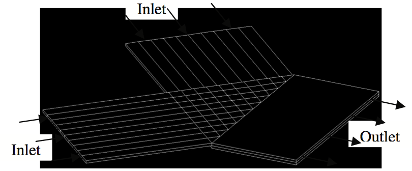
Figure 3. Geometry of the cross flow
This geometry can be constructed by machining the
channels inside the upper and lower part of the die since
the interface between them is open. It should also be noted
that since the velocity of the polymer is inherently 3D in
this flow, it is not possible to make a 2D geometry
representing cross flows.
Grid Generation
The required mesh to decompose the geometry to
finite volumes was generated in GAMBIT. Structured
cubic elements were generated for the geometry of the
crossed flow with the consideration of the flow pattern.
Using hexahedral elements, it is possible to achieve higher
accuracy of the results with much fewer grids. In addition
these types of grids are more desirable because modeling
the free surface is only possible with structured grids
normal to the approximate direction of flow. The
maximum skewness of the generated grids is calculated to
be 0.25 and the maximum aspect ratio of elements is 7.1,
which are in the range of acceptable values. There are a
total of 410,000 elements inside and outside the die.
Figure 4 shows the constructed grid in different locations
of the die.
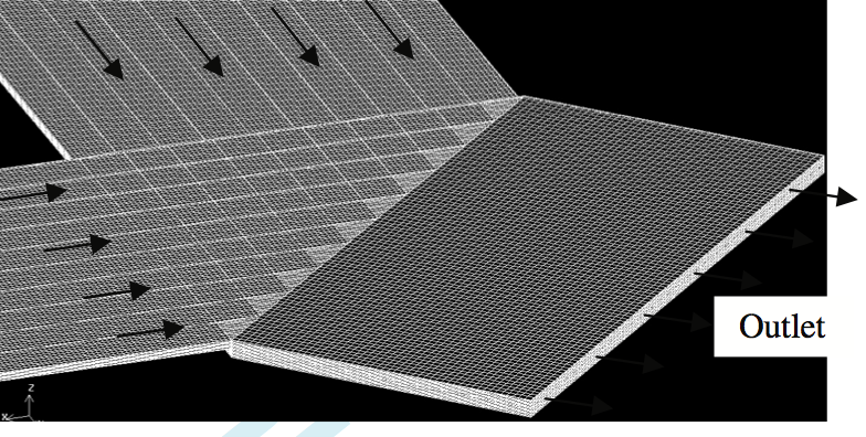
Figure 4. Structured grid on cross flow geometry
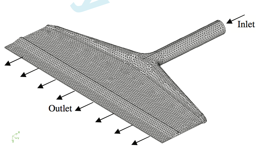
Figure 5. Unstructured grid on the geometry of the coat-hanger die
Due to the complexity of the coat-hanger die,
unstructured hexahedral elements were chosen for
decomposing the geometry into finite volumes. Figure 5
shows the generated mesh for the coat-hanger geometry
(mesh density is reduced here for demonstration purpose).
The mesh consists of 3,000,000 elements with the worst
skewness of 0.777 and worst aspect ratio of 3.5 which are
both in the range of acceptable limits.
Material Properties and Boundary Conditions
Two different models for material properties were
used to simulate the flow inside the die. The first model
considers the fluid to be Newtonian and defines a constant
viscosity. In this model stress and strain inside the flow
are linearly proportional. For this case the viscosity of the
fluid was taken to be 0.1 Pa.s for low viscosity and 220
Pa.s for high viscosity.
The second model was chosen based on the available
experimental results for one type of LCP. An experiment
based on capillary rheometer with capillary length of 20
mm and diameter of 1 mm has been done. This
experiment was done under isothermal condition where
the temperature was kept constant at 350°C. (Figure 6).
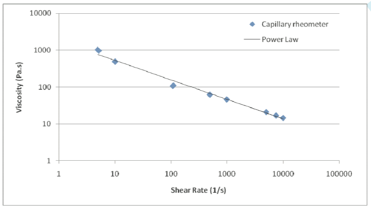
Figure 6. Viscosity of LCP as a function of shear rate used in the simulation
By looking at the curve of viscosity vs. strain rate on
a log-log scale, it appears that it can be modeled by the
power law model. Based on this information the nonNewtonian
power law model was used as a second model
to simulate the flow inside the die. In the power law
model, equation (1) is used in the constitutive equation to
model viscosity [5]:
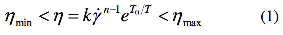
To find the parameters to substitute in this equation,
the automatic option of Polymat software was used.
Moreover, for defining this model completely, the minimum and maximum values of viscosity should be
given which was chosen to be the maximum and minimum
values in the capillary experiment. (See Table 1).
Three different boundary conditions were used to
define the boundaries of the geometry which include
velocity inlet, walls and outlet. The channels inside the die
were modeled as zero thickness walls with zero tangent
and normal velocities. Also, since there is no free wall
boundary condition, the flow outside the die is also
considered to be through a channel. It should be noted that
the interfaces between the upper and lower channels are
defined as an interface which mean two flows have
interaction.
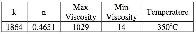
Table 1. Constants Used for Non-Newtonian Power Law Model
Solution Considerations and Results
FLUENT uses finite volume method to solve the
constitutive equations on the meshes [5]. One important
consideration before beginning the simulation is the
importance of inertia terms in the equations. Since most
polymers have high viscosity, flow is mostly driven by
pressure and the non-linear inertia terms can be neglected.
The importance of inertia terms can be found by
calculating the Reynolds number of the flow. In all the
following simulations, the inertia terms were included.
Ignoring the inertia terms helps with the convergence of
the solution since these terms introduce non-linearity to
the equations but it also reduces the accuracy of the results
especially when Reynolds number is not small. Steady
state first order pressure based implicit solver was used in
all cases.
Figure 7 shows the pathlines colored by the pressure
for the two cases of Newtonian constant viscosity and
non-Newtonian power law viscosity models. For
Newtonian flow, the value for the viscosity is chosen as
the mean value of the viscosities obtained from the
capillary rheometry experiment which is 220.1 Pa.s.
Figure 8 shows the velocity vectors at the lip of the
cross-flow die geometry. As can be seen, velocity vectors
change from -45 to 45 degrees across the thickness of the
film. Velocity vectors are always tangent to the
streamlines. In this study, the director of crystallines are
tangent to the streamlines which means that almost the
same biaxial pattern can be achieved using two cross
flows instead of complicated rotating dies.
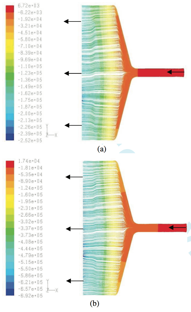
Figure 7. Pathlines colored by static pressure inside the coat-hanger geometry for the case of (a) constant viscosity and (b) power law
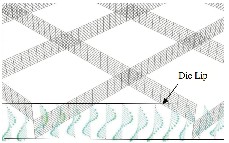
Figure 8. Velocity vectors across the thickness at the lip of the die (Newtonian model)
Figure 9 shows the result found by using the power
law model based on capillary rheometer. As can be seen
the change in direction of velocity vectors across the die is
very small and hard to recognize except for the vectors in
the vicinity of the fins.
The simulation of rheology inside the cross-flow die
has been done using two different Newtonian and one
non-Newtonian viscosity models. The first Newtonian
model simulation is done using a constant viscosity of 0.1
Pa.s (See Table II).
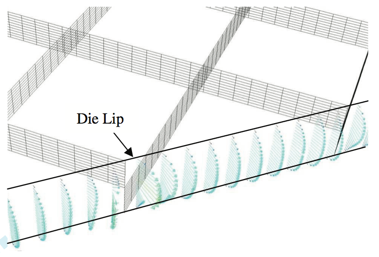
Figure 9. Velocity vectors across the thickness at the lip of the die (non-Newtonian model)
It can be seen from the velocity vectors that in this
case the relative importance of inertia terms forces the
fluid to keep its direction until it exits the die lip. The
second Newtonian model used the average value of the
viscosities obtained during the capillary rheometry
experiment which is 220.1 Pa.s. For this high value of
viscosity, inertia forces are negligible compared to the
viscous forces and flow reaches its fully developed
condition in a very short distance and the only change in
the velocity vectors are observed to be in vicinity of fins.
Since the maximum angle between two cross flows
depends both on inertia and viscous forces, this angle is
derived for several different Reynolds numbers based on
the thickness of the each crossed flow channel with
Newtonian model.
These results are shown in Figure 10. By increasing
the Re of the flow, the relative importance of the inertia
forces increases and we approach 90 degrees (from -45 to
+45 degrees). On the other hand, at very low Re, flow
approaches its fully developed condition and there will be
no difference in the angle.
Figure 10 shows that there is a turning point at around
Re=500 when the angle is 80 degrees and at lower Re the
maximum angle between the vector does not satisfy the
desired angle between the two flows.
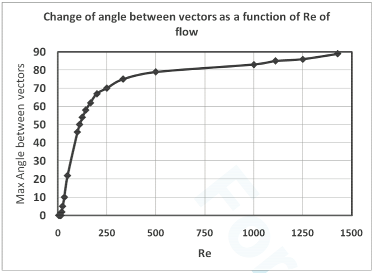
Figure 10. Change of angle between vectors as a function of Re of flow
The last simulation on the cross flow geometry is
done using the actual experimental results of the capillary
rheometer. In this case due to the shear thinning effect of
the viscosity, the pressure drop is less than the pressure
drop obtained for constant viscosity and also the velocity
profile at the die lip is more flat.
Discussion and Summary
The results of the simulations of the Newtonian and
non-Newtonian material models for the coat-hanger and
cross-flow die geometries are compared in Table 2. From
these results it can be observed that it is possible to obtain
the correct molecular orientation using this new crossflow
die geometry but for the orientation of the
crystalline. One solution for increasing the change in the
direction of velocity vectors can be increasing the number
of fins inside the die or increasing the angle between the
two cross flows. It is also clear that the design of the die
geometry is directly related to the material and processing
characteristics such as viscosity and inlet velocities.
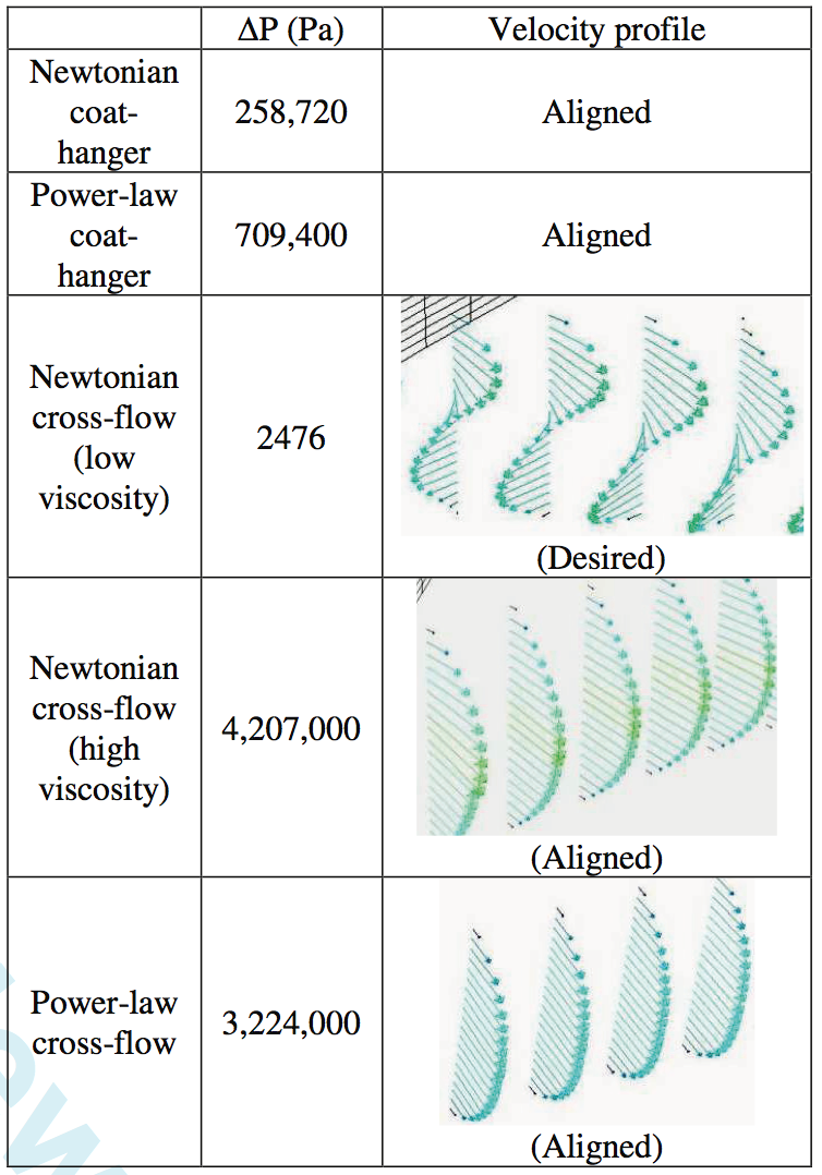
Table 2. Summary of the simulation results
References
1. R. Lusignea, K. Blizard and L. Rubin, High
Performance Processing For High Performance
Polymers, Mat. Res. Soc. Symp. Proc. Vol. 305,
1993.
2. B. Farrel and M. Lawrence, The processing of liquid
crystalline polymer printed circuits, Proceedings of
52nd Electronic Components and Technology
Conference, 2002.
3. R. Ahmad, R.F. Liang and M.R. Mackley, The
experimental observation and numerical prediction of
planar flow and die swell for molten polyethylenes, J.
Non-Newtonian Fluid Mech., 59 (1995) 129-153.
4. R. Lusignea, High-barrier packaging with liquid
crystalline polymers, TAPPI Journal, Vol. 80: No.6,
1997.
5. Fluent Documentations, Ver. 6.3, 2010.
Return to
Paper of the Month.