Die Design Effect on Internal Die Drool Phenomenon
Martin Zatloukal1,2, Jan Musil1
1 Centre of Polymer Systems, University Institute, Tomas Bata University in Zlin, Nad Ovcirnou 3685, 760 01 Zlin, Czech Republic
2 Polymer Centre, Faculty of Technology, Tomas Bata University in Zlin, TGM 275, 762 72 Zlin, Czech RepublicAbstract
In this work, the effect of die exit design on the
internal die drool phenomenon occuring during extrusion
of HDPE has been experimentaly investigated. It has been
revealed, that firstly, the effect of flared length and die
exit angle on the internal die drool intensity during
extrusion of HDPE has non-monotonic character and
secondly, flared dies are more stabilizing in comparison
with chamfered dies.
Introduction
During extrusion process, there is a tendency for some
of the extruded polymer materials to adhere to exit edges
or open faces of extrusion die from which the extruded
material emerges. The material so deposited on the die
exit, can build up into a large compact usually degraded
mass or can form drips, flakes or powder which
frequently break away from the die, adhere perseveringly
onto extruded product surface and thus damage it. This
effect is in extrusion art defined as undesirable
spontaneous accumulation of polymer melt at the die exit
face and it is termed like “die drool”, “drooling”, “die
lip build-up”, “die bleed”, “die plate-out”, “die
deposit”, “die drip” or “die moustache” and the
accumulated material is generally named “drool”[1, 2]. It
is generally accepted that there are two types of the die
drool phenomenon; “external die drool phenomenon”,
which is generated just at the end of the die due to the
extrudate free surface creation and negative pressure
generation (causing the suction effect) [2, 3] and “internal
die drool phenomenon”, which is initiated inside the
processing equipment as the results of degradation [4] or
flow induced molecular weight fractionation [5]. In fact,
there is number of material, processing and die design
based parameters promoting and suppressing the die drool
phenomenon and some of them have been recently
documented such as pressure fluctuations in screw [6],
volatiles, low molecular fractions of the polymer, fillers,
poor dispersion of pigments [8], die swell [4, 6],
processing near degradation temperature [7, 9], dissimilar
viscosities in blends [10], broadening molecular weight
distribution [11-12], increasing melt elasticity [5, 7], shark skin [2, 3], slip-stick phenomenon [5, 12-13], or
abrupt corners at the die lips [3, 14, 15] have been found
to promote die drool. On the other hand, chain branching
increase [5], polymer processing aids addition [10], using
ceramics dies [16] or dies with PTFE
chemically/physically locked in die wall [8], silicon
rubber coated surface of extrusion die [13], hard chrome
dies [17], flared [3, 14, 15] or chamfered [3] die exits,
have been found to reduce this phenomenon. With respect
to the stabilizing role of the die design, it was initially
believed that flared dies are so effective due to occurrence
of stress undershoot inside flared section [1]. However,
Ding et al. [18] mathematically modeled stress field inside
the flared section and they concluded that stress
undershoot is not the main reason for suppressing
accumulation of drool mass at the die lips. They have
suggested that the history of the stresses upstream of the
exit, not just their instantaneous values at die lips, governs
the die drool reduction in flared dies. Recently,
Chaloupková and Zatloukal [3] were able to correlate
stabilizing efficiency of die exit chamfering, die opening
and die exit flaring with negative pressure, pressure
gradient and normal component of the pressure gradient
during extrusion of the metallocene based LLDPE at
which the external die drool has occurred.
In this work, experimental analysis has been
performed for extrusion dies at which chamfer angle and
flared length were systematically varied in order to
understand the role of die design for the internal type of
die drool phenomenon as well as to explore the
knowledge about parameters which could allow more
efficient die design optimization.
Experimental
In this work, well stabilized unfilled virtually linear
HDPE polymer melt (HDPE Liten FB 29 E2009 3220
4479, extrusion grade, Unipetrol RPA, Czech Republic,
material characterization is summarized in our previous
work [12]) has been used. The internal die drool
measurements were performed on specially designed
extrusion line equipped by replaceable capillary, which
has already been used in our previous studies [5, 7, 12].
The line was consisted of conventional Plasti – Corder
2000 model (Brabender, Germany) single-screw extruder
with diameter D = 30 mm and L = 25D (standard singlethread
screw with compression ratio 4:1, and lengths of
zones: feed L
1 = 10D, compression L
2 = 3D, metering L
3
= 12D), transition annular part, specially designed annular
extrusion die, photo camera Canon 600D model (Canon,
Inc., Japan) with resolution of 18 Mpx equipped with
Canon macro lens EF 100mm placed near the die exit for
die drool visualization and finally draw-off mechanism.
The die drool experiments were performed as follows.
Extruder zones (from the hopper to the die) were heated
to T
1 = 150°C, T
2 = 155°C, T
3 = 160°C and T
4 = 160°C,
respectively by keeping the annular tube (connecting die
and extruder) and die exit temperature constant, T
5 = T
6 =
160°C. The low exiting temperature 160°C for the HDPE
melt was chosen to achieve highly pronounced
fractionation effect due to high efficiency of melt to store
elastic energy as well as to suppress any thermal/oxidative
degradation. Further, mass flow rate (MFR) was chosen
750g.hr
-1 (apparent shear rate 673 s
-1) to ensure that the
flow condition lies above the slip-stick phenomenon, i.e
in the “superflow” regime at which the die drool intensity
is the highest as shown in [12]. In order to measure
fractionated (drooled) polymer mass accumulated at the
die exit, the following methodology was used. The
extruder was stopped after 10 minutes of extrusion and
the accumulated material was carefully manually removed
from the die lip by a tweezer, weighted on a sensitive
analytical balance and the procedure was repeated three
times for each capillary to calculate standard deviation.
Before each set of three independent 10 minutes tests (for
given capillary), barrel, screw and all parts of the die have
been disassembled and perfectly manually cleaned.
Finally, die drool intensity has been expressed in
dimensionless form through buildup ratio BR (introduced
by Gander and Giacomin in [1]):
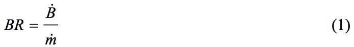
where m is total mass flow rate of extruded polymer melt
and B
. means buildup rate:
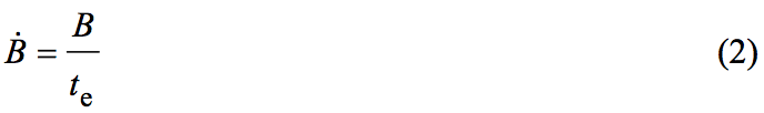
where B is the mass of accumulated die drool material on
the die exit face and t
e is total extrusion time of each test
(10 minutes in our case). To evaluate die exit design
effect on accumulated drool mass following stainless steel
capillaries were used. The straight capillary with abrupt
die exit edge angle of 0° having diameter D1 = 1.6mm and
L/D ratio of 9.375 (see Figure 1a) and its two
modifications: chamfered die (see Figure 1b) with three
different die exit angles (α = 15°, 30° and 45°) and flared
die (see Figure 1c) with four different flared lengths
(LC
1 = 1mm, 2mm, 5mm, 8mm) and one fixed die exit angle (α = 45°). For both modified dies, the outer
diameter DC
1 was kept to be 2mm.
Results and Discussion 
The effect of die exit angle and flared length
(expressed here in the dimensionless form as the flared
length, LC
1, divided by the capillary length, L = 15 mm,
i.e. by LC
1/L ratio) on the dimensionless buildup ratio is
provided in Figure 2a and Figure 2b, respectively. As can
be seen, this dependence has interestingly strongly nonmonotonic
character and secondly, flared dies are more
stabilizing in comparison with chamfered dies. In more
detail, there is one minimum for 15° die exit angle
(representing reduction of accumulated drool mass
intensity by 56%) and one minimum at 2/15
dimensionless flared length (for which drool mass
reduction is the highest, equal to 97%). The possible
explanation of non-monotonic buildup ratio vs. die exit
angle dependence could be understood through
“detachment point” and “effective length”, Leff., location
as depicted in Figure 3. Here the detachment point
represents location at which extrudate detaches metal die
(due to the melt pressure/normal stresses at the die exit,
adhesion at metal wall/flowing melt interface and
extensional stress induced by the extrudate draw off)
whereas the effective length, Leff., is the distance in which
fractionated low molecular weight species are in touch
with the extrudate free surface as well as with the die
wall. Clearly, if the Leff. is high, there is high probability
that the low molecular weight fractioned polymer is
effectively removed from the die exit region by the
moving extrudate (because it happend under high
pressure) and only small portion of it remains at the die
exit face. This could happen for the most stabilizing case
(i.e. die exit angle equal to 15° as visualized in Figure
3b). On the other hand, a decrease in the die exit angle
down to 0° or increase it up to 30° or 45° could
continuously decrease the Leff. down to zero resulting to
the extreme situation at which the low molecular weight
fractionated polymer is not removed from the die exit
region and only its intensive accumulation takes place at
the die exit face resulting in intensive die drool
phenomenon.
The flow situation inside flared section can also be
viewed as the special case of two-layer coextrusion (see
Figure 4) at which the low molecular weight species
(formed due to flow induced fractionation) represents the
low viscosity skin and the main polymer the high
viscosity core (flow viscosity curves measured on
Advanced Rheometrics Expansion System ARES 2000
for both layers are provided in Figure 5). Due to abrupt
channel opening at the die exit, low enough pressure,
normal stresses, adhesion and high extensional stress
from draw off “interface expansion” could take place
during which the low molecular weight layer decelerates,
expands in thickness and core layer starts to be separated
from the skin layer (detachment point) far away from the
die exit (effective length is high) at which low molecular
skin layer becomes intensively dragged with the core
extrudate layer out of the die, thus suppressing its
building up at the die exit face. Thus, increase in the
effective length, Leff., for given flared die leads to more
intensive drool suppression. It seems that for the given
HDPE polymer melt and chosen processing conditions
Leff. has maximum at 2/15 dimensionless flared length due
to low pressure and low normal stresses, which increase
the effect of the extensional stress from the draw-off on
the flow field in the upstream direction, i.e. the
detachment point is moved in the upstream direction too,
which is stabilizing. On the other hand, for the longer
dimensionless flared sections (5/15, 8/15), detachment
point presumably starts to move closer to the die exit (i.e.
Leff. decreases) due to increasing pressure and the normal
stresses in flared section resulting in smaller efficiency of
the extensional stress from the draw-off to influence the
flow field in the upstream direction i.e. the position of the
detachment point is moved more closer to the die exit,
which is destabilizing.
Conclusion
It has been revealed experimentally, that the effect of
die exit angle and flared length on the internal die drool
intensity during extrusion of HDPE has non-monotonic
character. It has been found that the optimum value for
the die exit angle and dimensionless flared length is 15°
and 2/15, respectively. It has been proved that flared dies
are more stabilizing in comparison with chamfered dies.
In more detail, 56% and 97% reduction in accumulated
drool mass has been achieved with respect to straight die
having abrupt die exit edge angle of 0° for the optimum
value of die exit angle and dimensionless flared length,
respectively, for the HDPE material and given processing
conditions. It has been suggested that suppresion
mechanism of the internal die drool phenomenon through
die exit modification can be understood throught the
balance between the melt pressure/normal stresses at the
die exit, adhesion at metal wall/flowing melt interface and
extensional stress induced by the extrudate draw off,
which can lead to flow situation at which low molecular
weight species are effectively removed from the die exit
region by the moving extrudate and only small portion of
them remains at the die exit face. This work suggests that
for the simulation based die design optimization with
respect to internal die drool phenomenon, fully
viscoelastic constitutive equation together with proper
boundary conditions (including adhesion forces between
die wall and polymer melt and considering the extensional
stresses due to extrudate draw off) should be utilized in
order to precisely determine the location inside the die at
which free surface of the extrudate starts to occur.
Acknowledgement
The authors wish to acknowledge Grant Agency of the
Czech Republic (Grant No. 103/09/2066) and Operational
Program Research and Development for Innovations co-funded
by the European Regional Development Fund
(ERDF) and national budget of Czech Republic, within
the framework of project Centre of Polymer Systems (reg.
number: CZ.1.05/2.1.00/03.0111) for the financial
support.
References
1. Gander, J. D., Giacomin, A. J., Polym. Eng. and Sci.
37(7), 1113-1126 (1997).
2. Chaloupkova, K., Zatloukal, M., Polym. Eng. Sci.
47(6), 871-881 (2007).
3. Chaloupkova, K., Zatloukal, M., J. App. Polym. Sci.
111(4), 1728-1737 (2009).
4. Hogan, T. A., Walia, P., Dems, B. C., Polym. Eng.
and Sci. 49(2), 333-343 (2009).
5. Musil, J., Zatloukal, M., Chem. Eng. Sci. 66(20),
4814-4823 (2011).
6. Klein, I., Plastics World 39(5), 112-113 (1981).
7. Musil, J., Zatloukal, M., Chem. Eng. Sci. 65(23),
6128-6133 (2010).
8. Kurtz, S. J., Szaniszlo, S. R., US Patent 5,008,056
(1991).
9. Holtzen, D. A., Musiano, J. A., Technical Papers,
Regional Technical Conference – Society of Plastics
Engineers (1996).
10. Priester, D. E., Annual Technical Conference –
ANTEC, Conference Proceedings 2, 2059-2061
(1994).
11. Musil, J., Zatloukal, M., Gough, T., Martyn, M.,
AIP Conference Proceedings 1375, 26-42 (2011).
12. Musil, J., Zatloukal, M., Chem. Eng. Sci., 81,
146-156 (2012).
13. Kulikov, O., Hornung, K., J. Non Newtonian Fluid
Mech. 124(1-3), 103-114 (2004).
14. Rakestraw, J. A., Waggoner, M. G., US Patent
5,458,836 (1995).
15. Ohhata, T. et al., US Patent 5,417,907 (1995).
16. Moore, S., Modern Plastics, 8, 37 (1994).
17. Musil, J., Zatloukal, M., Annual Technical
Conference – ANTEC, Conference Proceedings 2,
1181-1185 (2011).
18. Ding, F., Zhao, L., Giacomin, A. J., Gander, J. D.,
Polym. Eng. Sci. 40(10), 2113-2123 (2000).
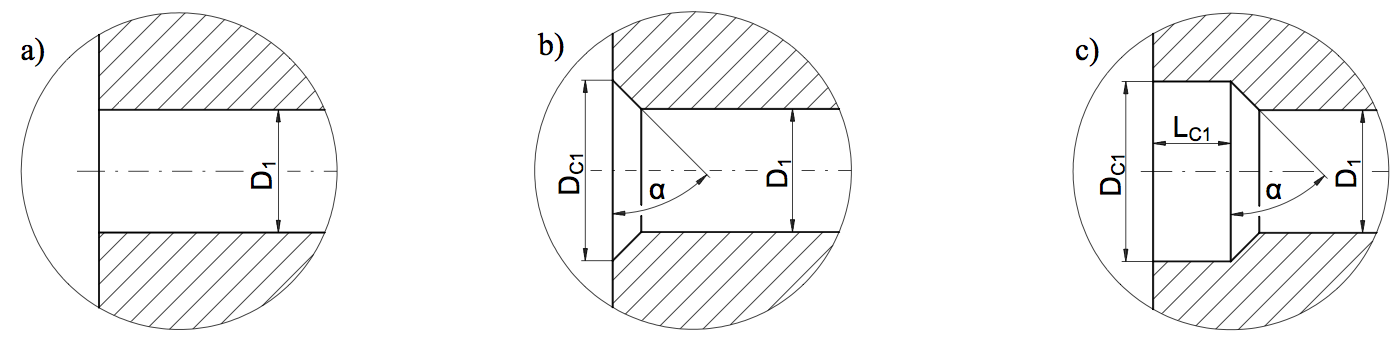
Figure 1: Detailed section views of capillary exit regions: (a) straight capillary, (b) chamfered die, (c) flared die.
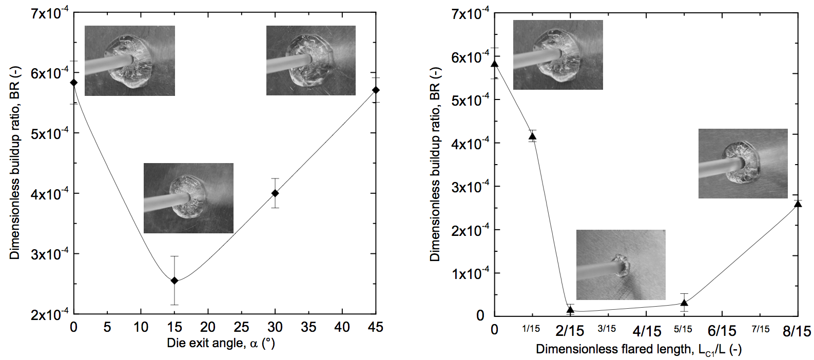
Figure 2: Effect of die exit design on dimensionless buildup ratio: (a) die exit angle effect, (b) dimensionless flared length effect.
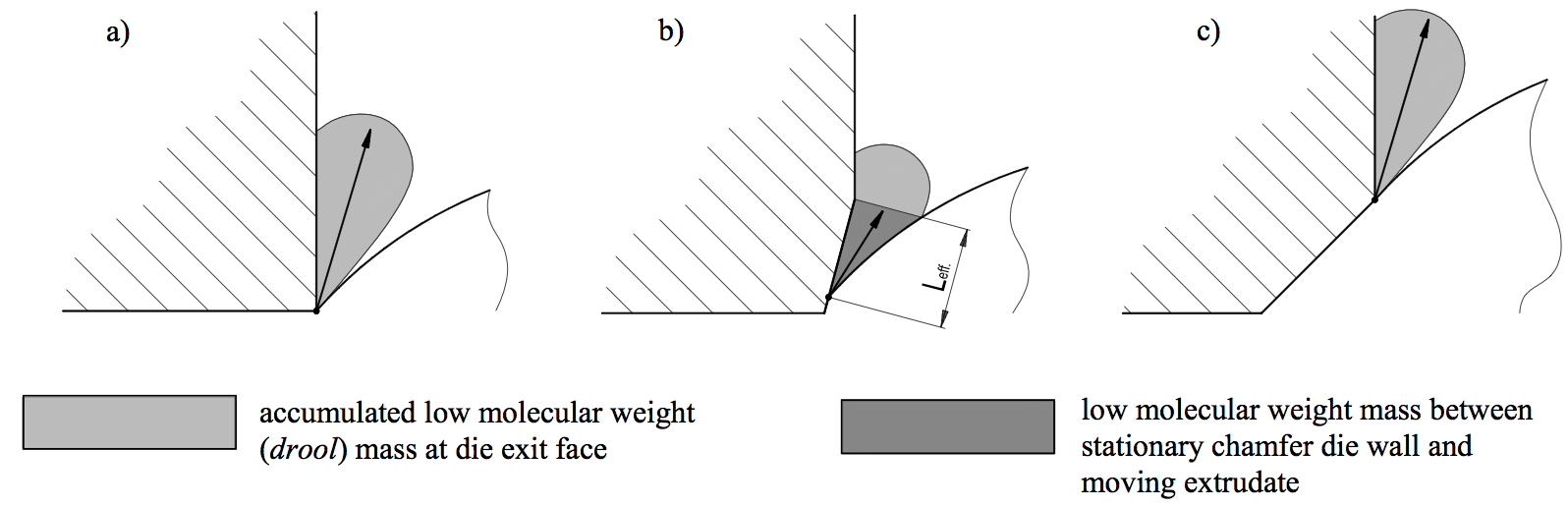
Figure 3: Effect of die exit angle on extrudate detachment and accumulation process of low molecular weight mass for (a) 0°, (b) 15°, (c) 45° dies.
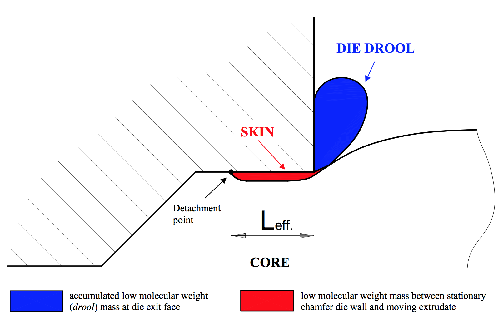
Figure 4: Visualization of the low viscosity skin (die drool layer) and high viscosity core (main polymer) inside and outside the die for the optimum 2/15 dimensionless flared length.
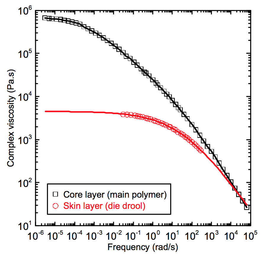
Figure 5: Frequency dependent complex viscosity for the die drool (skin) and main polymer (core) samples.
Return to
Paper of the Month.