Improving Thickness Uniformity with Proper System Design
Vol. 39 #1, Winter 2014
Flow disturbances that emanate from the extruder can cause thickness variations in a cast sheet or film coating. However, the size of the disturbance that results in the sheet or film will be dampened by the delivery system between extruder and die. The delivery system would include pipes, filters, mixers, valves or any other things in the flow stream. Proper design of the delivery system will minimize the size of a disturbance that reaches the product.
A model of the transient flow is used to analyze the dampening of the delivery system [1]. It is based on the impedance method for calculating hydraulic transients [2]. The model is used to identify the important factors and the quantitative relative importance of each.
Figure 1 shows a very simple example of a delivery system, and it lists the factors that are important to system damping of flow disturbances. Flow rate is given for sinusoidal flow at the inlet and exit of the system. An amplitude ratio is defined as the ratio of the amplitude of the exit flow disturbance divided by the amplitude of the inlet flow disturbance at the extruder, and it will be less than one.
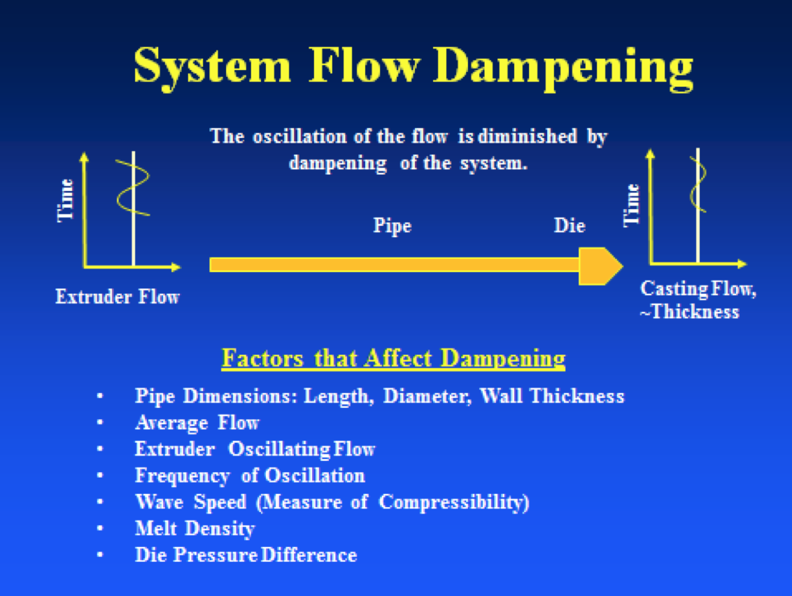
Figure 1. A simple example used to demonstrate the important factors to flow dampening in a polymer delivery system
Figure 2 shows an example for LDPE with specified values of the factors, and the amplitude ratio of the flow is given for these alternative factors of the system. A base case is given by which to judge changes.
Of importance is the wave speed of the polymer. This is a measure of the compressibility of the polymer melt which includes the size and end constraints of the conduit. The wave speed determines the amount of flow disturbance that will be absorbed by the delivery system through bulk compression of the melt and stretching of the conduit.
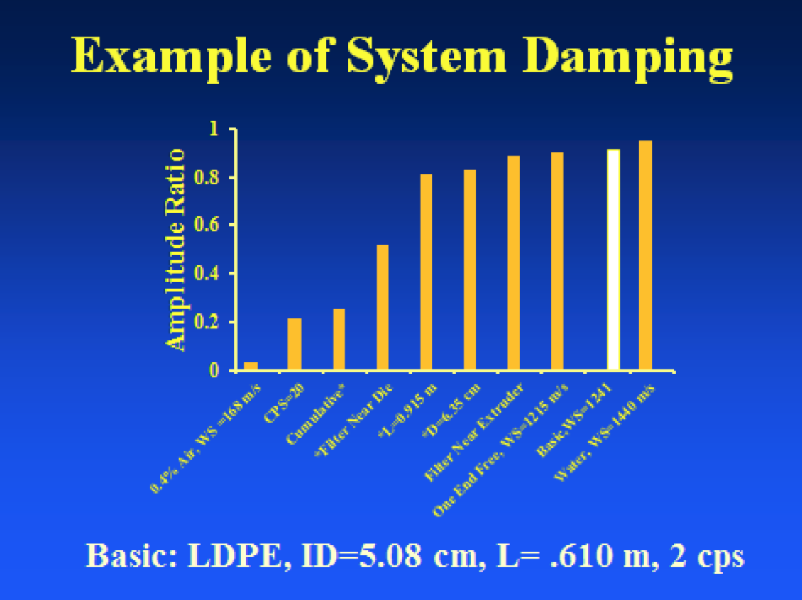
Figure 2. The damping ratio resulting from changes in the system layout.
Several factors are shown that give an amplitude ratio of between 0.8 and 0.9. For comparison, the amplitude ratio for water is shown to be over 0.90 as water (wave speed =1440 m/s) is less compressible than LDPE melt (wave speed=1241 m/s).
The location of a filter is shown to be a significant factor. Locating the filter as near as possible to the die lowered the amplitude ratio to about 0.55. When near the extruder the amplitude ratio is nearly 0.9.
A cumulative effect for making the pipe longer, larger diameter and putting the filter near the die lowers the amplitude ratio to about 0.24.
The frequency of the oscillation of 20 cps is shown to be a major factor. Higher frequency will al- ways lead to lower amplitude ratios.
Entrapped air or gas is shown to be a major factor. A value of 0.4% by volume dramatically lowers the wave speed to 168 m/s, and almost eliminated the transmission of the disturbance. Ironically, purging of the system to eliminate gas bubbles in the product will hinder damping and thickness uniformity.
Every system will react differently depending on the cited factors. The math model can be easily used to identify which factors are most effective in increasing damping and improving thickness uniformity for different systems.
References1. Derezinski, Stephen J. “Calculating Surge Dampening in Melt Delivery Systems,” Society of Plastic Engineers Conference Proceeding ANTEC 1997, 1997, pp. 341-346.
2. Streeter, Victor L. and E. Benjamin Wylie, Hydraulic Transients, Chapter 4, McGraw-Hill Book Company, New York, 1967.
- Stephen J. Derezinski, Ph.D. Extruder Tech, Inc.