Producing Microlayer Blown Film Structures Using Layer Multiplication and Unique Die Technology
Joseph Dooley, Jeff Robacki, Steve Jenkins, Patrick C. Lee, and Robert Wrisley
The Dow Chemical Company, Midland, MIAbstract
Many polymers are extruded through blown film
dies to produce monolayer and multilayer films. The
most popular style of die in use today to produce
blown films is the spiral mandrel die. This type of die
can be used effectively for many polymers in
structures containing up to approximately 10 layers.
This paper will discuss technology in which layer
multiplication techniques are combined with unique
die geometries to produce microlayer blown film
structures with significantly greater numbers of layers.
Introduction
Coextrusion is a common method used for
producing multilayer blown films. Coextrusion is a
process in which two or more polymers are extruded
and joined together in a feedblock or die to form a
single structure with multiple layers. This technique
allows the processor to combine the desirable
properties of multiple polymers into one structure with
enhanced performance characteristics. The
coextrusion process has been widely used to produce
multilayer sheet, blown film, cast film, tubing, wire
coating, and profiles [1-6].
Many polymers are extruded through blown film
dies to produce monolayer and multilayer films. The
most popular style of die in use today to produce
blown films is the spiral mandrel die [7]. This type of
die can be used effectively with many polymers to
produce monolayer and multilayer blown films.
However, this type of die normally cannot be used to
produce microlayer blown films because the complex
flow path in these dies can disrupt the continuity of the
layers.
This paper will discuss a new, unique microlayer
coextruded blown film technology in which a
microlayer structure is formed using feedblock and
layer multiplication technology and then processed
through a unique blown film die to produce a
microlayer blown film structure.
Coextrusion
A breakthrough technology was originally
developed by Schrenk and Chisholm to produce
multilayer coextruded planar structures [8, 9]. In this
technique, the layers are joined together in a device
called a feedblock prior to the die. This layered
structure is then processed through a single die
manifold. This feedblock technique is shown
conceptually in Figure 1.
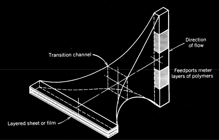
Figure 1. Feedblock coextrusion to make multilayer planar products.
Another method used to produce planar
coextruded structures is with a multimanifold die. In
this technology, planar layers are formed individually
in separate die manifolds and then the layers are joined
together before the exit of the die.
Microlayer Coextrusion
The feedblocks and dies discussed in the previous
section are suitable for producing multilayer structures
with typically ten layers or less, which is adequate for
many industrial applications. However, there have
been multilayer structures developed that require
hundreds or thousands of layers to produce unique
properties [10-13]. Among these properties are
enhancements in mechanical and optical properties.
In order to produce film or sheet structures with
hundreds or thousands of layers, new techniques were
developed to produce those structures. Standard feedblock techniques would not allow this many layers
because of mechanical difficulties in joining so many
layers. Methods to produce hundreds of layers were
developed by Schrenk and co-workers [14-16]. A
common technique is shown schematically in Figure 2.
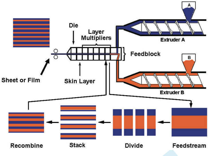
Figure 2. The microlayer coextrusion process.
Figure 2 shows how layers are joined together in a
feedblock to form a three-layer structure. However, at
the end of the feedblock, a layer multiplier is added
that vertically divides the layers and then stacks and
recombines the structure in order to increase the total
number of layers. A series of layer multipliers can be
added to significantly increase the number of layers in
the final structure.
One important point to be made with this type of
microlayer coextrusion is that this process was
developed to produce flat sheet or cast film products.
A large portion of the film industry uses the blown
film process rather than the cast film process because
of the biaxial orientation that is imparted to the film
producing a product with more balanced properties.
This process will be described in more detail in the
following section.
The Blown Film Process
A schematic diagram of the blown film process is
shown in Figure 3. In this process, an extruder is used
to melt and forward molten resin into an annular film
die. Air is injected into the center of the annular die to
inflate the polymer bubble. The bubble is cooled by
an air ring that blows air on the surface of the bubble
to lower its temperature until it becomes solidified.
Above the die, a stabilizing cage may be used to
minimize movement of the bubble as it is collapsed in
the collapsing frame to make a flat film. This film is then pulled over idler rolls and fed into a film winder
to make the finished film roll.
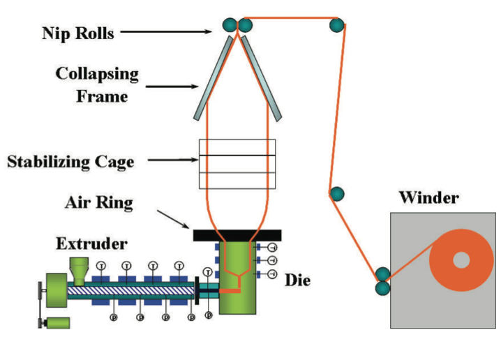
Figure 3. The blown film process.
A key part of this process is the blown film die.
The blown film die takes the polymer melt from the
extruder and shapes it into a tubular geometry to form
the film bubble. This bubble must be uniform in
thickness and temperature in order to form a uniform
bubble. The different types of annular blown film dies
that can be used in this process are described in the
following section.
Blown Film Dies
A schematic diagram of a spiral mandrel die is
shown in Figure 4 [17]. In a spiral mandrel die, the
cylindrical surface of the inner mandrel is spirally cut
with grooves that become shallower as you progress
down the channel. Since several spiral grooves are
typically cut into a single manifold, there is flow down
the channel grooves and also a leakage flow across the
lands separating the grooves. This combination of
flows produces a more uniform flow rate at the exit of
the annular die and so a more uniform thickness in the
resulting film. This type of design essentially
eliminates the weld line difficulties seen in previous
film dies. The application of this technology to the
blown film industry was a significant breakthrough and
spiral mandrel dies are now the dominant style of die
used today in the blown film industry.
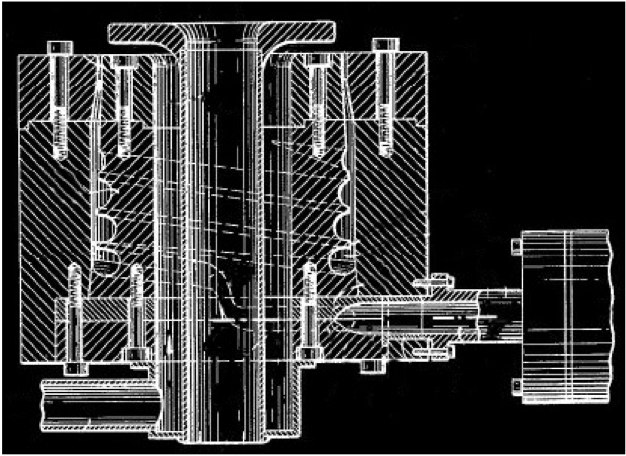
Figure 4. A single layer spiral mandrel die.
In order to make a multilayer blown film structure
using spiral mandrel technology, a separate die
manifold must be made for each layer. This concept is
illustrated in Figure 5. Note in this figure how each
layer is formed by a separate spiral mandrel manifold
at a different radial distance from the center of the die.
The individual annular flow streams are formed and
then joined together near the exit of the die. If a
multilayer feed stream was fed to the entry of this style
of die, the layered structure could be destroyed as
portions of the layers flowed down the spirals but other
portions flowed across the land areas and over the next
spiral. This combination of flows would produce an
overall flow pattern that could disrupt the continuity of
the original layered melt fed to the die.
In this style of die, increasing the number of layers
in the structure is accomplished by increasing the
diameter of the die to make room for more spiral
mandrel manifolds for each new layer. This tends to
limit the number of layers that can practically be
produced on this type of die because larger diameter
dies have longer residence times and more surface area
which can lead to degradation of the polymers being
processed in the die.
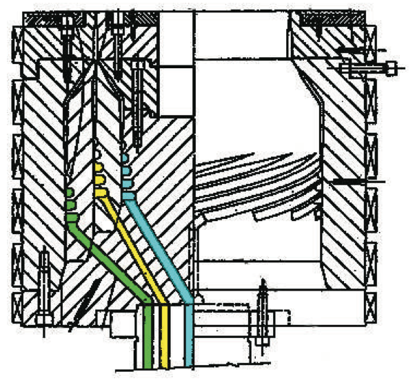
Figure 5. A multilayer spiral mandrel die.
Another style of spiral mandrel die has been
developed in which the spiral channels are cut on the
surface of a flat plate rather than on the surface of a
cylinder. In this type of die, there can be multiple
overlapping spirals cut into the same plate just as was
done in the previous cylindrical spiral mandrel dies.
By bolting two of these flat plates with matching
grooves together, a spiral flow channel is created.
Because of the dimensions of these large flat plates,
these dies are sometimes referred to as “pancake” style
dies.
One advantage of using a flat plate die for
producing coextruded structures is the ability to stack
plates on top of each other. This is shown in Figure 6.
This figure shows a schematic diagram of multiple
stacked plates bolted together in which each set of
plates produces one layer. Each layer is added
sequentially to the previous layer as the structure flows
up the die towards the exit. This figure also shows a
photograph of a commercial stacked plate die used to produce coextruded films.
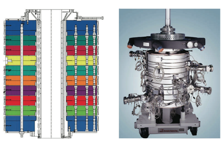
Figure 6. A multilayer stacked plate or “pancake” die.
This style of die is very versatile relative to
changing the number of layers in a structure. By
increasing or decreasing the number of plates stacked
together, it is relatively easy to change the number of
layers in the final film structure. Structures containing
up to 11 layers have been demonstrated using this type
of die design. However, stacking more die plates to
increase the number of layers beyond 11 layers
becomes difficult due to pressure drop considerations
and lack of space for more extruders.
Microlayer Blown Film Concept
As discussed in the previous section, making
multilayer blown films containing more than 11 layers
is currently not feasible using existing technology.
Technology has been developed by Schirmer [18, 19]
in which thin annular disks are stacked together to
form an annular structure with up to approximately 30
layers. This technology is similar to what is shown in
Figure 6 but the plates are very thin and use a specific
plate geometry and stacking to produce more layers.
Making the plates thinner allows more layers to be
added sequentially but a limit is reached when the
pressure drop through all of the die plates becomes too
large to process the structure. This process can also
produce non-uniform layer thicknesses in the film.
The new concept for producing microlayers in a
blown film is based on using a feedblock and layer
multipliers in combination with a unique film die.
This technique would overcome many of the pressure
drop and residence time issues seen with the existing
technology.
There are two main considerations to be taken
into account when feeding a microlayer structure into
a film die: (1) protecting the very thin microlayers as
they flow from the feedblock to and through the die,
and (2) the design of the geometry of the die to allow
the layers to flow smoothly through the die while
maintaining the microlayered structure.
Protecting the microlayered structure as it flows
through the process can be done by encapsulating the
microlayers with another layer. This is shown
schematically in Figure 7. In this figure, an
encapsulation die is shown schematically on the left
producing a circular encapsulated structure on the
right. This diagram shows a single core material
being encapsulated by another layer but conceptually
the single core material could be replaced by a
microlayer structure.
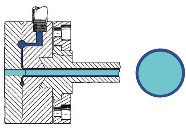
Figure 7. A schematic drawing showing an encapsulation die on the left producing an encapsulated structure on the right.
The next consideration is the geometry of the die
to be used. As was discussed previously, a spiral
mandrel type die would tend to disrupt the layered
geometry fed to it and so this type of die geometry
probably cannot be used for a uniformly microlayered
structure.
Another type of die that could be used for this
process is a crosshead style die. In this type of die, the
flow is fed to the front side of the die where it is split
such that half of the material flows around one side of
the die while the other half flows around the other side
of the die. These two flows then join together on the
back side of the die forming a weld line region. Once
rejoined, the material then flows annularly around the
central mandrel.
Figure 8 shows two photographs of the front and
back sides of a crosshead style die. The photograph
on the left shows the front where the flow is split into
two halves to flow around the central mandrel. The
photograph on the right shows the back of the die
where the two flow channels rejoin to form the annular
structure. Note that at the point that the two flows join
together, there is a place at which the two flows must
“weld” back together to form a single flow stream.
This area is sometimes referred to as the “weldline”
area.
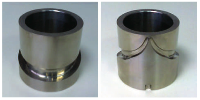
Figure 8. Photographs showing the front (left) and back (right) geometries of a crosshead style die.
The difficulty encountered with feeding a
microlayer structure into a crosshead style die occurs
in the weldline area. When the microlayer structure
flows around the central mandrel and tries to rejoin in
the weldline area, the microlayers do not form a
continuous structure since there is a high probability
that each individual microlayer will not align perfectly
with the corresponding microlayer from the opposite
side of the die which leads to the discontinuity of
layers at the weldline. This difficulty can be overcome
by using technology developed and patented for
making coextruded blown barrier films [20-22].
The technology developed for making coextruded
blown barrier film consisted of encapsulating the
barrier polymer melt with a separate layer and then
processing that through a crosshead style die in which
the ends of the flow channels were overlapped. This
overlapping of the layers in the weldline area produced
a film structure with equivalent barrier properties in
the weldline area compared to other areas of the film
and eliminated the need to join the layers exactly
together in the weldline area. Dies containing this type
of technology are commercially available.
A diagram comparing an encapsulated melt in a
standard crosshead die and a die in which the ends of
the channels have been overlapped is shown in Figure
9. We have taken this technology and adapted it to
produce microlayer blown films. This diagram shows
a single core material being encapsulated by another
layer but the single core material can be replaced by a
microlayer structure and overlapped as well.
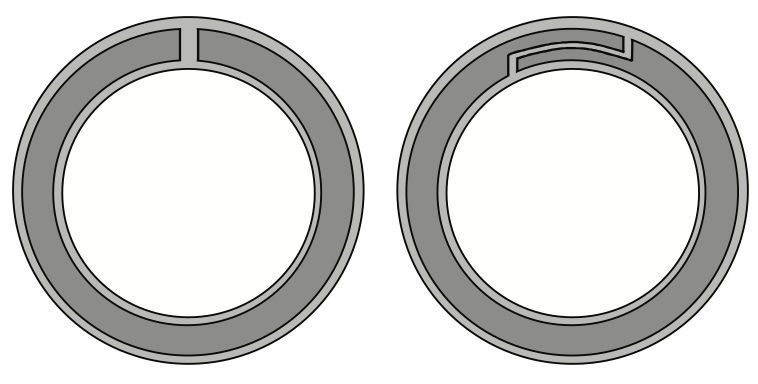
Figure 9. Comparison of an encapsulated melt in a standard crosshead die and a die in which the ends of the channels have been overlapped.
Proof of Concept for Microlayer Blown Film
In order to validate the concept of using a
feedblock, encapsulation, and a crosshead die with an
overlap geometry to produce a microlayer blown film,
a 7 inch diameter laboratory blown film line was
modified.
Microlayer Blown Films Containing 30+ LayersAs a first attempt to make a microlayer blown
film, a laboratory blown film line was modified by (1)
adding a feedblock to join together materials from two
extruders for a core layer, (2) adding a layer multiplier
to increase the number of core layers, and (3) adding
an encapsulation extruder and feedblock to
encapsulate the layered core structure. This equipment
modification produced a microlayer core structure
which was subsequently fed to a blown film die
containing a crosshead style manifold with an overlap With these line modifications in place, an
experiment was carried out to try to make a microlayer
blown film on this line. The first attempt consisted of
processing a low density polyethylene (LDPE) resin,
DOWTM LDPE 501 resin, manufactured by The Dow
Chemical Company, in all the extruders. The final
film structure would contain 27 layers from the
feedblock/layer multiplier combination, 2
encapsulation layers (top and bottom), and 5 additional
layers from the other 5 die manifolds for a total of 34
layers. A photograph of the film bubble with this
structure as it is being produced is shown in Figure 10.
This photograph is being taken from a vantage point
that shows the overlap side of the die. Note that the
film appears clear and uniform with no discernable
optical difference between the main part of the bubble
and the overlap area.
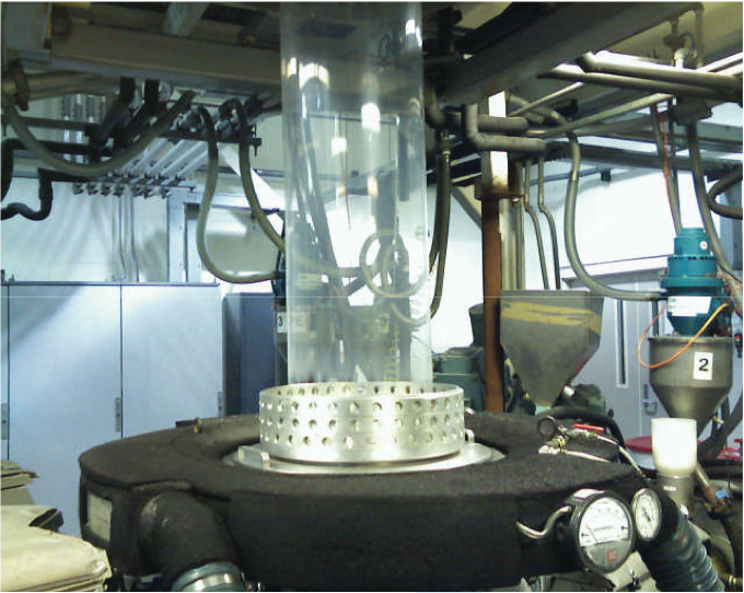
Figure 10. A microlayer blown film bubble containing 30+ layers.
Figure 11 shows a photomicrograph of a crosssection
the microlayer blown film containing 30+
layers. The core microlayers are pigmented to make
them more visible during microscopy. This sample
showed that all of the microlayers were intact in the
structure.
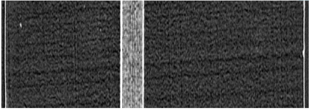
Figure 11. A photomicrograph of a microlayer blown film containing 30+ layers.
This photomicrograph shows that the microlayer
core containing 27 layers was about 8% of the total
thickness of the 2 mil film. This makes each
microlayer approximately 0.006 mils or 0.15 microns
thick.
A second set of microlayer blown films were
produced with different materials in the core layers in
order to improve our ability to differentiate between
the layers during microscopy. These films had
microlayer cores composed of alternating layers of
DOW
TM LDPE 501 resin and AFFINITY
TM 1140
Polyolefin Plastomer resin, both manufactured by The
Dow Chemical Company. The density difference
between these resins allowed the use of Atomic Force
Microscopy (AFM) to produce images showing the
layered structure.
Figure 12 shows an AFM image of this microlayer
blown film containing the LDPE and polyolefin
plastomer resins with a thicker core. This core layer is
approximately 25% of the total thickness compared to
only 8% in the previous structure.
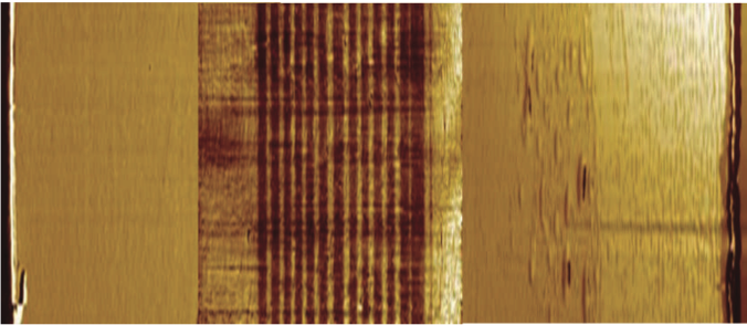
Figure 12. An AFM image of a microlayer blown film containing 30+ layers with a thicker microlayer core.
One important question that needed to be
answered in these blown film trials was whether the
microlayer structure would remain intact all the way
around the film tube and in the overlap area. AFM
images are shown in Figures 13 and 14 with expanded
views of the core microlayers near the die entry region
and near the die overlap for our microlayer film with a
core composed of alternating layers of LDPE and the
polyolefin plastomer resins. These images show the
layers are intact near the die entry and remain so in the
overlap area. Note in Figure 14 that the total number
of core layers has doubled since we are now
overlapping those layers on the back side of the die.

Figure 13. An AFM image showing an expanded view of the core microlayers near the die entry region in a microlayer blown film containing 30+ layers.

Figure 14. An AFM image showing an expanded view of the core microlayers near the die overlap region in a microlayer blown film containing 30+ layers.
Figure 15 plots the thickness of the 27 microlayers
near the die entry in the core of the microlayer blown
film described previously, but with a total overall
thickness of 4 mils. Note that the thickness of the individual layers is fairly uniform and averages about 1
micron in thickness.
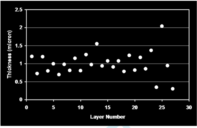
Figure 15. The layer thickness distribution for the core microlayers in a microlayer blown film containing 30+ layers.
Microlayer Blown Films Containing 100+ Layers
Our next target in making microlayer blown films
was to significantly increase the number of microlayers
in the core of the film.
Using the modified line set-up, the 27 layers
created previously were processed through a layer
multiplier to make 108 core layers. These 108 core
layers were then sent through the encapsulation die to
coat the outside of the microlayer core structure.
Figure 16 shows a sample taken from near the exit of
the encapsulation feedblock showing the encapsulated
108 layer structure before it enters the die. This
sample was taken to ensure that the layers were intact
prior to their entry into the die. Note the four bands of
black and white pigmented layers. These bands
correspond to the channels in the layer multiplier. The
surface layers in each band are white and so there are
two white layers between each band producing a white
layer with twice the thickness of the other layers.
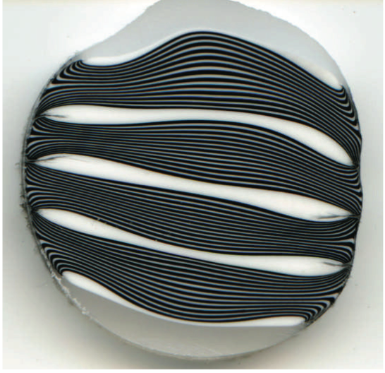
Figure 16. A photograph showing the encapsulated microlayer structure prior to the die entry.
With these new line modifications in place, an
experiment was carried out to try to make a microlayer
blown film on this line. Once again our first
experiment consisted of processing low density
polyethylene resin in all the extruders. The final film
structure would contain 27 layers from the microlayer
feedblock multiplied four times by the layer multiplier
to produce 108 layers, 2 encapsulation layers (top and
bottom), and 4 additional layers from the other 4 die
manifolds for a total of 114 layers. A photograph of
the film bubble with this structure as it is being
produced is shown in Figure 17. This photograph is
being taken from a vantage point that shows the
overlap side of the die. Note that this 100+ layer film
appears clear and uniform with no discernable optical
difference between the main part of the bubble and the overlap area.
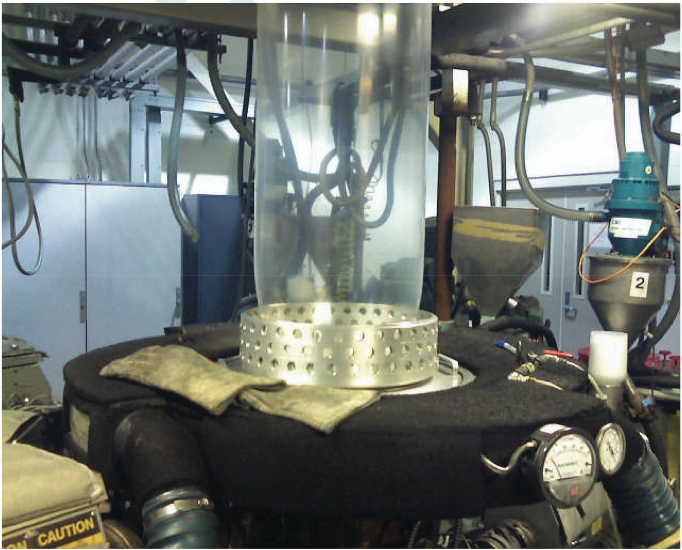
Figure 17. A microlayer blown film bubble containing 100+ layers.
Figure 18 shows an AFM image of a 100+
microlayer blown film containing LDPE and
AFFINITY
TM Polyolefin Plastomer resins. An
important question that needed to be answered was
whether the 100+ microlayer structure would remain
intact in the film. The AFM image shown in Figure 18
is an expanded view of the core microlayers near the
die entry region that shows the layers are intact near
the die entry.
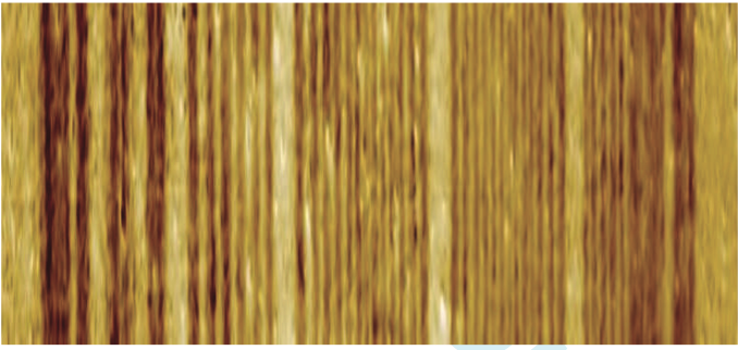
Figure 18. An AFM image showing an expanded view of the core microlayers near the die entry region in a microlayer blown film containing 100+ layers.
Just as Figure 18 shows an AFM image of the core
microlayers near the entry region of our microlayer
blown film containing 100+ layers, Figure 19 shows a
Transmission Electron Microscopy (TEM) image of
the core microlayers near the overlap region of the
microlayer blown film containing 100+ layers.
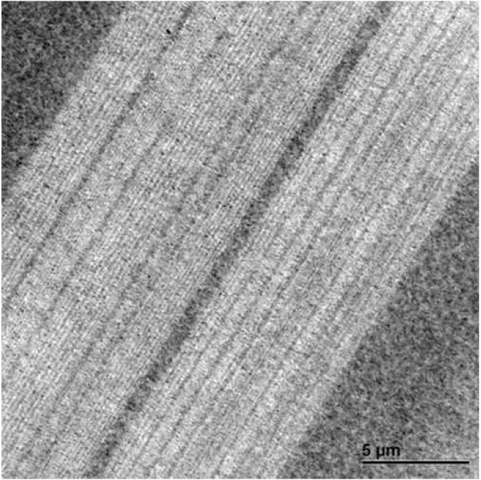
Figure 19. A TEM image showing an expanded view of the core microlayers near the overlap region in a microlayer blown film containing 100+ layers.
Figures 18 and 19 show the 100+ layers in our
microlayer blown film are intact near the die entry and
remain so in the overlap area. Note in Figure 19 that
the total number of core layers has doubled since we
are now overlapping those layers on the back side of
the die and so this figure actually shows more than 200
microlayers in the overlap area.
Conclusions
A new, unique microlayer coextruded blown film
technology has been developed in which a microlayer
structure is formed using feedblock and layer
multiplication technology and then processed through
a unique blown film die to produce an annular blown
film structure. This technology has been used to
produce microlayer blown films with over 100 layers.
A patent case has been filed covering this new
processing technology.
References
1. L.M. Thomka and W.J. Schrenk, Modern Plastics, (April 1972).
2. C.D. Han, J. Appl. Poly. Sci., 19 (1975).
3. W.J. Schrenk, Plastics Engineering, 30, 65, (March 1974).
4. J.A. Caton, British Plastics, 3, (1971).
5. L.M. Thomka, Plastics Engineering, 18, (Feb. 1973).
6. C.R. Finch, Plastics Design Forum, 59, (Nov./Dec. 1979).
7. J. M. Dealy and K. F. Wissbrun, Melt Rheology and Its Role in Plastics Processing, p. 537, Van Nostrand Reinhold, New York, 1990.
8. D. Chisholm and W.J. Schrenk, U.S. Patent 3,557,265 (January 19, 1971).
9. W.J. Schrenk, D.S. Chisholm, K.J. Cleereman, and T. Alfrey Jr., U.S. Patent 3,759,647 (September 18, 1973).
10. J. Im, and W. J. Schrenk, Coextruded Microlayer Film and Sheet, J. of Plast. Film & Sheeting,4,104, (April 1988).
11. T. Alfrey, Jr., and W. J. Schrenk, Multipolymer Systems, Science, 208, 813, (May 1980).
12. T. Alfrey, Jr., E. F. Gurnee, and W. J. Schrenk, Physical Optics of Iridescent Multilayered Plastic Films, Polym. Eng. and Sci., 9, 6, 400, (November 1969).
13. M. F. Weber, C. A. Stover, L. R. Gilbert, T. J. Nevitt, and A. J. Ouderkirk, Giant Birefringent Optics in Multilayer Polymer Mirrors, Science, 287, 2451, (March 2000).
14. W. J. Schrenk, U.S. Patent 3,884,606, (May 20,
1975).
15. W. J. Schrenk, R. K. Shastri, and R. E. Ayres,
U.S. Patent 5,094,788, (March 10, 1992).
16. W. J. Schrenk, R. K. Shastri, and R. E. Ayers,
U.S. Patent 5,094,793, (March 10, 1992).
17. H. Upmeier, U.S. Patent 3,689,192, (September 5, 1972).
18. H. G. Schirmer, U.S. Patent 5,762,971, (June 9, 1998).
19. H. G. Schirmer, U.S. Patent 6,413,595, (July 2, 2002).
20. U.S. Patent 6,685,872, (February 3, 2004).
21. J. Dooley, S. Jenkins, and J. Naumovitz, An Experimental Study of the Flow of an Encapsulated Polymer Melt Through a Unique Blown Film Die, SPE-ANTEC Technical Papers, 47, 386 (2001).
22. K. Xiao, S. Jenkins, and J. Dooley, Novel Methods to Process High Barrier PVDC, TAPPI, Polymers, Laminations, Adhesives, Coatings, & Extrusions Conference, Paper 3-1 (2008).
Key Words: Microlayer, Coextrusion, Blown Film,
Dies, Spiral Mandrel, Crosshead, Feedblock, Layer
Multiplication.
Return to
Paper of the Month.