Coextrusion Layer Thickness Variation-Effects of Geometry on Layer Rearrangement
Joseph Dooley and Ravi Ramanathan - The Dow Chemical Company, Midland, MI
IntroductionCoextrusion is a process in which two or more polymers are extruded and joined together in a feedblock or die to form a single structure with multiple layers. This technique allows the processor to combine the desirable properties of multiple polymers into one structure with enhanced performance properties. The coextrusion process has been widely used to produce multilayer sheet, blown film, cast film, tubing, wire coatings, and profiles (1-6).
Previous work on the layer thickness uniformity of coextruded structures has centered primarily on the effects of differing polymer viscosities in the individual layers (7-11). These differences in viscosities result in a phenomenon known as "viscous encapsulation" in which the less viscous layer tends to encapsulate the more viscous layer producing non uniform layer thicknesses.
In this study, the effect of the geometry of the polymer flow channel on the layer thickness uniformity of multilayer coextruded structures was investigated. This work extends the previous research done by the authors on the geometric effects in the flow of coextruded polymeric structures (12). In order to minimize the viscosity effects, the coextrusion experiments were conducted with identical materials in each layer.
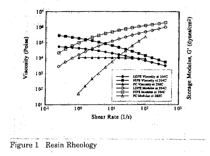
ExperimentalThe resins chosen for this study were a high impact polystyrene resin (STYRON* 484), a. low density polyethylene resin (LDPE 641I), and a polycarbonate resin (CALIBRE* 300·22) all manufactured by The Dow Chemical Company. The rheological properties of these resins are shown in Figure 1. Two layer coextruded structures were made using the same polymer in each layer with different colored pigments added to each layer to determine the location of the interface. In order to clarify these two layer results and to further study the flow patterns produced, additional experiments were run using structures containing 165 layers (again pigmented to allow observation of the interfaces) under the same processing conditions used in the two layer experiments. This paper will focus primarily on the two layer coextruded structure results.
The primary coextrusion line used in this study for the two layer experiments consisted of a 31.75 mm (1.25 inch) diameter, 24:1 L/D single screw extruder for the substrate resin and a 19.05 mm (0.75 inch) diameter, 24:1 L/D single screw extruder for the cap resin. These extruders were attached to a feedblock that was designed to produce a two layer structure consisting of a 20% cap layer and 80% substrate layer. Attached to the exit of the feedblock was a die containing one of the different channel geometries studied. Experiments were run on several different lines with different extruder sizes and feedblock designs, all producing similar results.
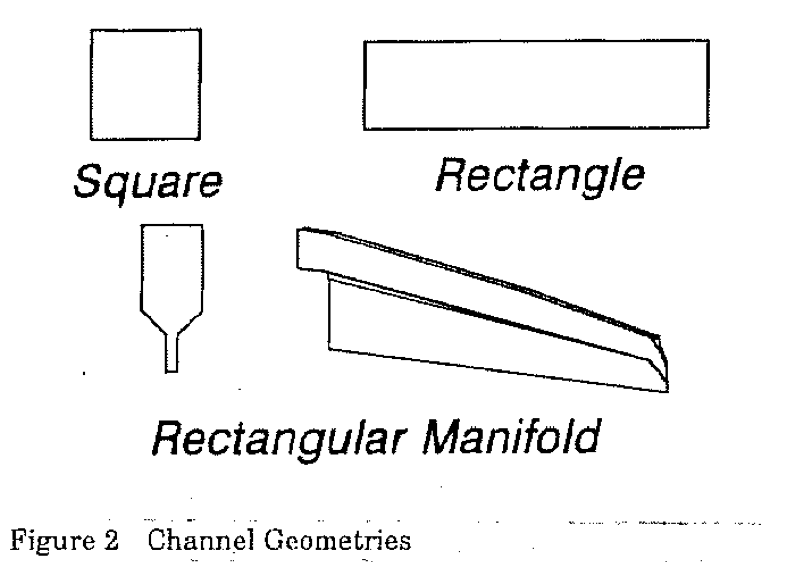
Three different channel geometries were used in this study; a square channel, a rectangular channel, and a rectangular manifold channel. These geometries are shown schematically in Figure 2. The square and rectangular geometries were chosen since they are used in the design of feedblocks and dies while the rectangular manifold channel is meant to simulate half of a coat-hanger type die. The square channel had sides that were 0.95 cm (0.375 inch) long. The rectangular channel had a 4:1 width to height aspect ratio with the width measuring 2.54 cm (1.0 inch) and the height being 0.635 cm (0.25 inch). The rectangular manifold channel was designed based on principles used in the design of coat-hanger type die manifolds to produce uniform output across the die exit. The rectangular distribution manifold maintains a constant 4:1 aspect ratio down its entire length and starts with dimensions identical to those of the rectangular channel. This allows direct comparisons to be made between the two channels. The length of each of the die channels was 60.96 cm (24 inches).
For a typical experiment, the coextrusion line was run for a minimum of thirty minutes to ensure that steady-state conditions had been reached. The normal extrusion rate was approximately 8.6 kg/hr (18.9 lb/hr) for the polystyrene resin which would give a wall shear rate in the range of 30 to 40 reciprocal seconds. Both the polystyrene and polyethylene resins were extruded at 204°C while the polycarbonate resin was extruded at 260°C. When steady state was reached, the extruders were stopped simultaneously and the coextruded material was cooled while still in the die channel. After it had cooled to room temperature, the polymer "heel" was removed from the die and examined. This procedure allowed the major deformations of the interface(s) to be analyzed.
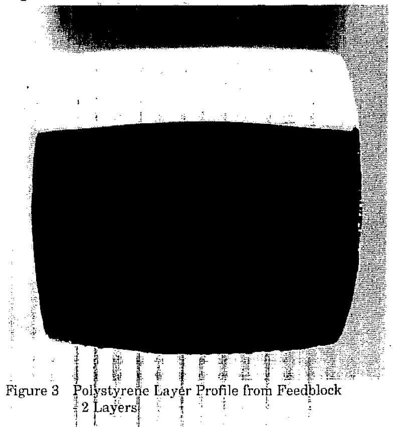
ResultsAn initial coextrusion experiment was run through the feedblock only (with no die attached) to ensure that the ]ayers were uniform in thickness al the exit of the feedblock before they entered the die. Figure 3 shows the layer profile for the polystyrene resin extruded from both extruders at 204°C. The substrate layer of polystyrene was pigmented black and the cap layer pigmented white so that the interface could be clearly distinguished between the two layers. A series of experiments revealed no significant influence of the presence of low levels of pigments on the layer rearrangement. Note that the layers ere very uniform in thickness producing a flat interface. The results discussed below are organized in terms of the channel geometries, starting with the square channel and progressing through the rectangle and the rectangular manifold.
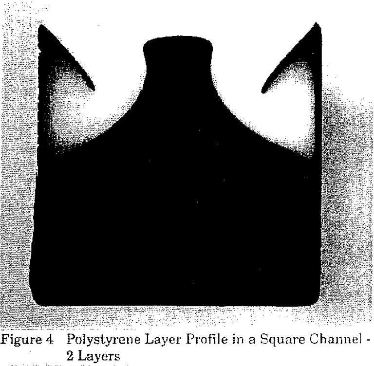
The next experiment consisted of running the same polystyrene resin through the system with an attached die containing a square cross-sectional shape (0.95 cm X 0.95 cm). Results from experiments using the square die have been discussed previously (12) but will be briefly reiterated here for comparison purposes. A cross-sectional cut of this sample at approximately 50 cm downstream from the feedblock is shown in Figure 4. This cut shows a thin black substrate layer moving up along the channel walls while the interface in the center of the coextruded structure was moving up towards-the top of the channel. Note also that the black substrate material that moved along the walls turned after it reached the corner and moved back towards the center at approximately a 45° angle. Viscous encapsulation principles do not explain these layer rearrangement results. It should also be reiterated at this point that the same polymer was being extruded in each layer of this structure in order to minimize any effects due to differences in viscosity.
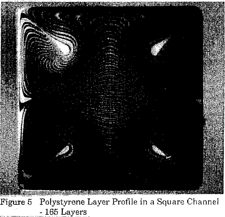
In order to better understand the layer distribution inBide the square channel, a polystyrene sample with 165 alternating black and white layers was extruded and is shown in Figure 5. This cut was taken at the same position as the two layer sample shown in Figure 4. This figure shows that the movement is symmetrical within each quadrant as material moves along the channel walls into the corners and then toward the center or the channel along the 45 degree diagonal line.
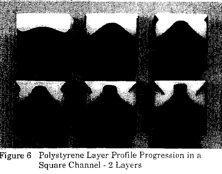
The layer rearrangement shown in Figure 4 occurred at a distance of approximately 50 cm from the feedblock. The layers rearrange progressively from the entry as the polymer flows down the channel producing a more distorted layer thickness profile as the distance travelled increases. This phenomenon is shown in Figure 6. In this figure the layer interfaces are shown at distances from the entry or the channel of approximately 5, 20, 30, 40, 50, and 58 cm (viewed from the top left hand corner to the bottom right corner of the figure, respectively).
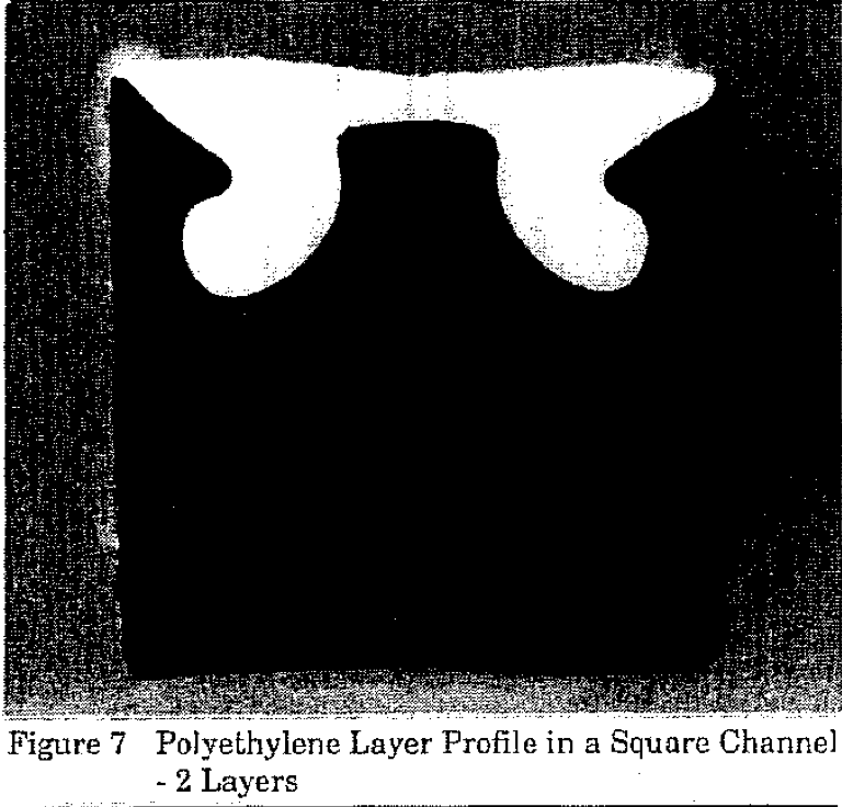
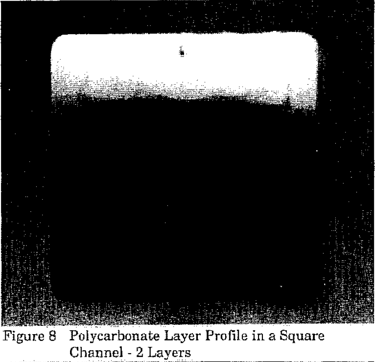
Results similar to the polystyrene sample were obtained for the polyethylene resin extruded through the square channel. This is shown in Figure 7 by a sample taken at a distance of 50 cm from the entry or the die. However, very little layer rearrangement was observed in the sample produced using the polycarbonate resin as is clearly shown in Figure 8.
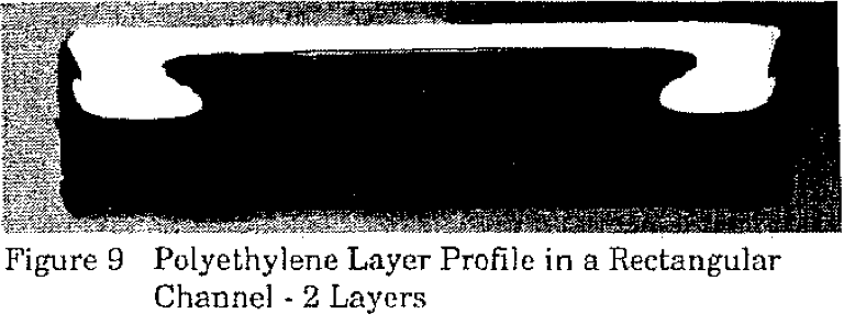
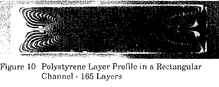
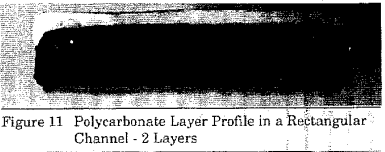
When the resins were run through the die channel with the rectangular: cross-section, substantial layer rearrangement was again observed for the polystyrene and polyethylene resins but not for the polycarbonate resin. A section cut from the two layer polyethylene sample and one from the 165 layer polystyrene sample taken from the rectangular channel are shown in Figures 9 and 10. The results for the polycarbonate sample are shown in Figure 11.
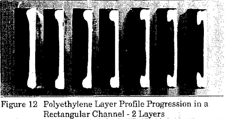
The size and intensity of the secondary flow regions appear to be quite different when compared to the results or the square channel. However, as was observed with the square channel, the layers continue to rearrange as the polymer flows down the channel. This is shown in Figure 12 for the two layer polyethylene sample. This sample is shown with cuts made at intervals of 7.6 cm (3 inches) down the channel with the cut on the left being nearest the feedblock while the cut on the right was taken near the exit of the die.
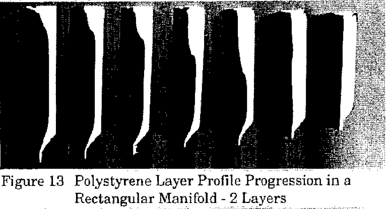
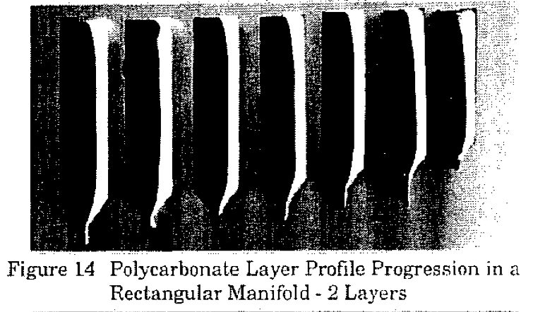
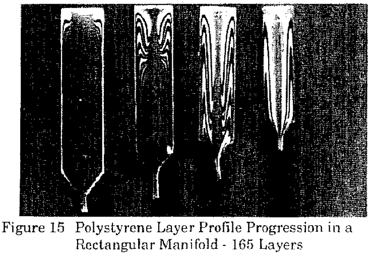
When the three resins were extruded through the rectangular manifold channel, a significant amount of layer rearrangement occurred once again in the polystyrene and polyethylene samples but not in the polycarbonate sample, Figures 13 and 14 show a series of cross-sectional cuts made at 7.6 cm (3 inch) intervals down the rectangular manifold channel for the two layer polystyrene end polycarbonate samples, respectively. Again the cut on the left was made nearest to the feedblock while the cut on the right was near the end of the manifold. Figure 15 shows a series of cuts for the polystyrene sample containing 165 layers.
DiscussionAs was discussed in a previous paper (12), one hypothesis that has been advanced to explain the movement of the layers in the polystyrene and polyethylene resins is the possible existence of secondary flows of the polymers in the channels. Secondary flows (flows perpendicular to the main flow) have been predicted for viscoelastic fluids in non-circular channels (13) but were thought to be small in magnitude compared to the bulk flow of the fluid (14). The predicted flow patterns for a viscoelastic fluid flowing through a square channel have been shown previously to contain eight recirculation zones or vortices, two each per quadrant (12,16-18).
These secondary flow patterns are consistent with the layer rearrangement seen in both the polystyrene and polyethylene resins in square channels (Figures 4-7) in that they would cause material to flow along the wall towards the corner and then back down towards the center of the channel at a 45° angle. The polycarbonate resin, however, does not show this movement (Figure 8). This may be because it exhibits less elastic behavior than the other resins, as is indicated by the storage modulus values shown in Figure 1.
The layer rearrangement observed in the rectangular channel for the polystyrene and polyethylene resins is similar to that seen in the square channel but is elongated along the major axis (width direction) of the rectangle (see Figures 9 and 10 for the two layer polyethylene sample and the 165 layer polystyrene Samples, respectively). This channel geometry appears to cause the vortex associated with the major axis to increase while decreasing the minor axis vortex, correspondingly. Although the vortices in the rectangular channel have shifted positions compared to those in the square channel, they are still present in the polyethylene and polystyrene samples. Once again, however, the polycarbonate resin did not show much movement of the layers as is shown in Figure 11.
The progression of the layer movement for the two layer polyethylene sample is shown in Figure 12. This figure shows that the progression of the layer movements is very similar to that seen in the square channel. The main difference between the square and rectangular samples appears to be the location and magnitude of the vortices round in each quadrant.
The flow patterns for the polystyrene sample in the rectangular manifold channel is shown in Figure 13. Note that although the layer ratio at the entrance of the manifold is 80/20 (substrate I cap layer) for the two layer sample, the ratio is approximately 50/50 by the time the structure reaches the end of the manifold. Again, the polycarbonate sample showed much less layer movement as is shown in Figure 14.
It appears that the layer profiles seen in the polyethylene and polystyrene resins in the rectangular manifold channel are produced by a combination of the vortices formed in the corners of a rectangular channel and the leakage of the material out the bottom of the channel. The movement of layers in the top corners of the manifold are very similar to the movements seen in the rectangular channel shown in Figure 12. However, it appears that the farther the material moves down the channel, the leakage flow becomes a larger percentage of the flow and pulls the layers that have moved in the upper section of the channel down towards the bottom of the channel. This movement is even more obvious in the 165 layer polystyrene sample shown in Figure 15. This figure shows that the leakage flow comes primarily from the center of the lower part of the channel. This combination of flow patterns will produce a fairly uniform layer pattern near the entry of the manifold but the layers near the end of the channel will be very distorted. This may be one mechanism to explain why coextruded structures of polymers with matching viscosities can sometimes produce products with non-uniform layer thicknesses. This could also explain why measurements of individual layer thicknesses in sheet products tend to show poorer distribution near the edges of the sheet compared to the center.
These results have many implication for the coextrusion of viscoelastic polymers. Since the layer movements observed occurred without any differences in viscosity between the layers, this implies that layer rearrangement may occur in coextrusions in which the polymer viscosities are well matched. Also, since the layers continue to rearrange as the polymer nows down the channel, these results also imply that this geometric effect will become more pronounced in sheet dies as they are scaled up to larger widths.
ConclusionsIt has been shown experimentally that coextruding identical polymers through channels of various geometries can cause the layers to rearrange. This layer rearrangement may be caused by secondary flows that occur in different channel geometries due to the elastic characteristics of the polymer.
Layer rearrangement of identical polymers implies that even resins with viscosities well matched for coextrusion may experience non-uniform layer thicknesses when coextruded though large dies. This effect can be minimized by the choice of the polymer and the die channel geometry.
The layer rearrangements observed in the three resins studied appear to follow the trend of increasing layer rearrangement with increasing elastic characteristics. In this study, the polystyrene resin showed the most layer rearrangement, followed by the polyethylene resin and finally the polycarbonate resin which showed little movement.
The effect of increasing the channel aspect ratio from a square to a 4:1 rectangle appears to change the location and magnitude of the secondary flow regions.
The flow in the rectangular manifold channel shows a combination of the secondary flows observed in the rectangular channel with the leakage flow seen in typical distribution manifolds. This produces a flow pattern that is fairly uniform at the manifold entry but becomes more distorted as the polymer flows down the channel.
AcknowledgementsThe authors would like to thank Kun Hyun and Walt Schrenk for many useful suggestions and interesting discussions relating to this work. We would also like to thank Kevin Hughes, Tom Van Conett, and Bob Wrisley for their help in preparing the coextruded samples.
DisclaimerNothing herein is meant to imply a license or other right to use the information contained in this paper as respects any patents of-The Dow Chemical Company or others.
References1. L.M. Thomka and W .J. Schrenk, Modern Plastics, (April 1972)
2. C.D, Han, J, Appl. Pol. Sci., 19, (1975)
3. W.J. Schrenk, Plastics Engineering, (March 1974)
4. J.A. Caton, British Plastics, 3, (1971)
5. L.M, Thomka, Package Engineering, 18, (Feb, 1973)
6. C.R. Finch, Plastics Design Forum, 69, (Nov./Dec. 1979)
7. J.H. Southern and R.L. Ballman, App. Polym. Sci., 20, (1973)
8. A.E. Everage, Trans. Soc. Rheo., 17, (1973)
9. B.L, Lee and J.L, White, Trans. Soc. Rheo., 18, (1974)
10. J.H. Southern and R.L. Ballman, J. Polym, Sci., 13, (1975)
11. A.A. Khan and C.D. Han, Trans. Soc. Rheo., 20, (1976)
12. J. Dooley and B. Hilton, Society of Plastics Engineers Technical Papers, Volume XXXIX, p.3364, (1993).
13. A.E. Green and R.S. Rivlin, Quart. Appl. Math., 14, (1966)
14. C.D. Han, "Rheology in Polymer Processing," p. 130, Academic Press, New York, (1976)
15. P. Townsend, K. Walters, and W.M. Waterhouse, J Non-Newtonian Fluid Mech., 1, (1976)
16. A.G. Dodson, P. Townsend, and K. Walters, Comput. Fluids, 2, (1974)
17. S. Thangam and C.G. Speziale, Acta Mechahica, 68, (1987)
18. J.A. Wheeler andE.H. Whissler, Trans. Soc. Rheol., 10, (1966)
* Trademark of The Dow Chemical Company
Return to
Best Papers.
