Design of Two-Stage Extractor-Screws
Dr. Paul H. Squires, Principal Consultant - DuPont Company
SummaryA basis for design of two-stage extractor screws is developed with special focus on determinng optimum design of the final pumping section to maximize pressure-generating capability. Departure from the conventional square-pitch helix angle of 17.7 deg appears justified in this section of the screw where pressure-development capability is critical to successful performance. Optimization can product gains of 5 to 30% in pressure (or in corresponding length reductions) - the exact benefits depending on the non-newtonian behavior of the melt and on the optimization strategy selected.
IntroductionTwo-stage single-screw extractor-extruders have been used for many years in processing polymers from which it is necessary to remove residual vapors. Moisture (absorbed and adsorbed) and trace monomer or solvents from polymerization are the most common vapors to be removed. The economics of today increasingly favor use of reclaimed resin. More often than not, this resin will contain unacceptably large amounts of moisture. Conventional forced-convection dryers will continue to have application, but consideration of cost is causing processors to take a harder look at extractor-extruders. Increased use of fillers - many of which carry moisture, air, or other vapors into the resin - also contributes to interest in extraction during extrusion.
Although the word "extrusion" is used here, "injection molding" frequently can be substituted. Similar needs and solutions often apply to both - assuming, of course, that we are addressing a molding process incorporating screw-melting rather than ram-melting. Abundant recent literature (1-18) attests to the attention being given to extraction during extrusion and injection molding.
Objective of This StudyThe extractor-extruder is called upon to convey and melt the plastic, to convey the melt into an extraction section where free volume is provided for disengagement and removal of vapors at atmosphere or sub-atmospheric pressure, and to pump the devolatilized melt out of the extruder against some elevated pressure. The task of designing an extractor-extruder thus is formidable. It requires that the designer call upon engineering principles when available, and upon experience to bridge the inevitable gaps in known engineering fundamentals.
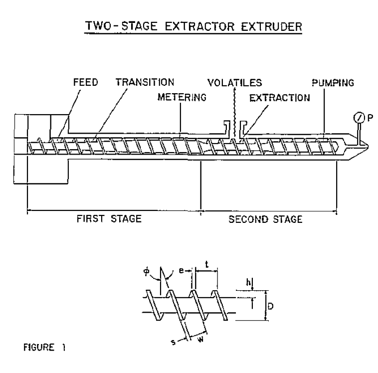
Design of a typical single-screw extractor-extruder is shown in Figure 1. The task of melting the plastic is compromised by the fact that available length is limited, but otherwise the task is similar to that faced in a conventional non-extraction screw. Abundant literature, not referenced here, exists. It therefore is assumed for purposes of this discussion that design of the feed, melting, and metering portions of the screw is known. The design task is made somewhat easier by the fact that this first metering section is not required to develop pressure, since it discharges into the extraction section which operates at atmospheric or sub-atmospheric pressure.
Single-screw extractor screws normally are used for removing only relatively small quantities of moisture or solvent - typically less than one or two weight percent. The vapor pressure of the fugitive component at the prevailing melt temperature usually exceeds the pressure in the extraction section. Flash boiling thus occurs. Bubble nucleation, growth, and disengagement during the typical four to ten second residence time in the extraction section dictate extraction effectiveness under these conditions. There exists no substantive technical literature on this mechanism for devolatilization in polymer systems. The role of molecular diffusion, surface renewal, and film evaporation has been examined in commendable studies by Latinen (19) Coughlin and Canevari (20), Roberts (21), and most recently by Biesenberger (22). A theoretical basis exists for calculating the channel depth required in the extraction section to provide a specified ratio of melt-to-vapor area in the screw channel (23).
The objective of this current study is to provide an engineering basis for optimum design of the final pumping section of a two-stage single-screw extractor-extruder.
Process Requirements in Pumping SectionThe pumping section must pump melt out of the ext.ruder at a rate dictated by the melting and metering section of the screw and against the pressure at the discharge end of the screw. Extrusion rate is governed solely by the melting and metering section of the screw. Rate is independent of discharge pressure except for transient disturbances which alter the inventory, i.e., the filled length, in the pumping section. Because of this, the term "pumping section" is applied to this final section of the screw. The term "metering section" is reserved for the shallow section of screw upstream from the extraction section.
Discharge pressure typically can range from 500 to 8,000 psi for extrusion processing. In an injection molding machine, the screw pressure during retraction usually is less than 1,000 psi. This low pressure would simplify the design task were it not for the offsetting limited length of screw usually available in molding machines.
Performance of the pumping section is a go or no-go scenario. A pumping section which falls only slightly short of being able to pump against the discharge pressure at the rate at which melt is being supplied from the upstream sections of the screw is inoperable. Melt will back into and fill the extraction section, and then flow out the vent opening.
Since length of the screw which can be used for pumping is limited, our specific objective becomes that of optimizing design of the pumping section to minimize the length needed to develop the discharge pressure or, equivalently, to maximize pressure generation in the pumping length available.
Theory For Design OptimizationAs early as 1953 Carley, Mallouk, and McKelvey (24) recognized that optima exist in channel. Depth and helix angle with respect to pressure development. Rauwendaal (25) recently advocated use of metering sections of optimum design, but did not extend his consideration to design of two-stage screws. Reasons exist for not viewing these .optima as important in the metering section of conventional single-stage screws. The feed and transition sections in such a screw invariably dominate performance; the metering section serving more as a "dynamic choke" than as a critical pump. Secondly, the optimum design - at least with respect to helix angle - is rather broad (26-29). Finally, of course, is the consideration of convenience and cost of using helix angles other than the industry-accepted 17.7° square pitch. These arguments, except perhaps for the last, are not applicable to the pumping section of a two-stage screw.
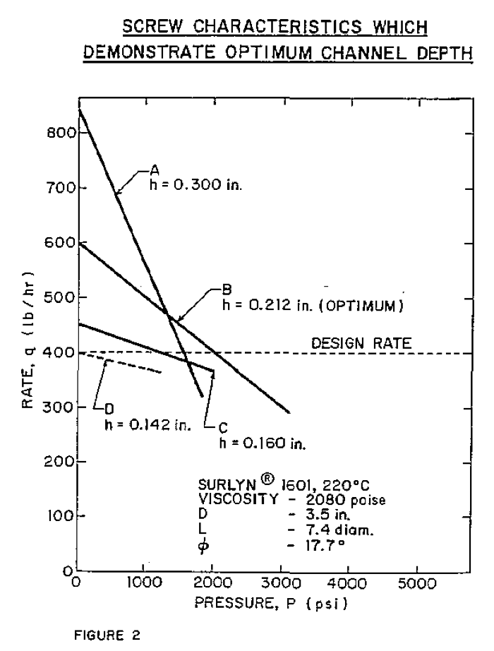
The information in Figure 2, based on the later design example, shows that an optimum depth must exist in the pumping section. At 600 lbs/hr, screw B develops a higher pressure than either the deeper screw A or the shallower screw C. A screw shallower than screw D would be incapable of delivering 400 lbs/hr against any positive discharge pressure.
Expressions for optimum channel depth and helix angle are developed in the Appendix. For the pumping section of an extractor screw, rate is an independent variable set by design of the upstream portions of the screw. For this reason, the optimization equations developed here retain throughput rate, q, as an explicit input variable. This is in contrast to the approach taken by others (24-29). Also, the simplifying assumption of vanishingly narrow flight width has not been made here; the optimization expressions of this current study are valid for multi-flighted screws with finite flight width. The assumption of a shallow, flat-plate model hills been retained.
As shown in Appendix I, for a given rate and helix angle the optimum channel depth, h*, which results in maximum pressure generation is given by

where b = ns/πD. If this same flow rate were to exist in a screw identical except for depth, but with zero pressure gradient, i. e., under drag flow conditions, it follows from Appendix Equation A7 that

where h
D is the required drag flow depth. Substitution of Equation 2 into Equation 1 gives

Thus, the optimum channel depth is 1.5 times the drag flow depth, h , at the same helix angle.
As shown in Appendix II, for a given rate and channel depth the optimum helix angle, theta*, is given by

Rapid convergence of Equation 4 to a solution for helix angle is obtained through conventional numerical equation-solving techniques.
If both channel depth and helix angle simultaneously are optimized, then the expression for h* given by Equation 1 can be substituted for h in Equation 4. If this is done, there results

where theta*o is the optimum helix angle if channel depth simultaneously is optimized. This optimal helix angle is independent of polymer properties and rate; it is a slowly-varying function only of the number of flights and of the ratio of flight width to diameter. Numerical techniques provide a rapidly-converging solution for theta*o in Equation 5.
If the flight width becomes vanishingly small, Equation 5 reduces to

which agrees with the results obtained from the previous simpler models in which flight width was ignored (24-27, 29).
An expression for the pressure which can be generated by the pumping section is given by Appendix Equation A11. Thus,

Let us now illustrate the application of these concepts to design of the pumping section for a typical extractor screw. The process requirements, operating conditions, and certain screw dimensions which have been assumed are summarized in Table 1.
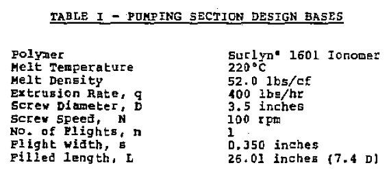
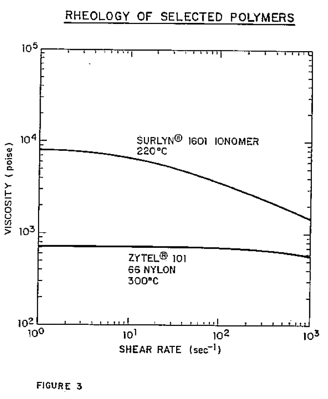
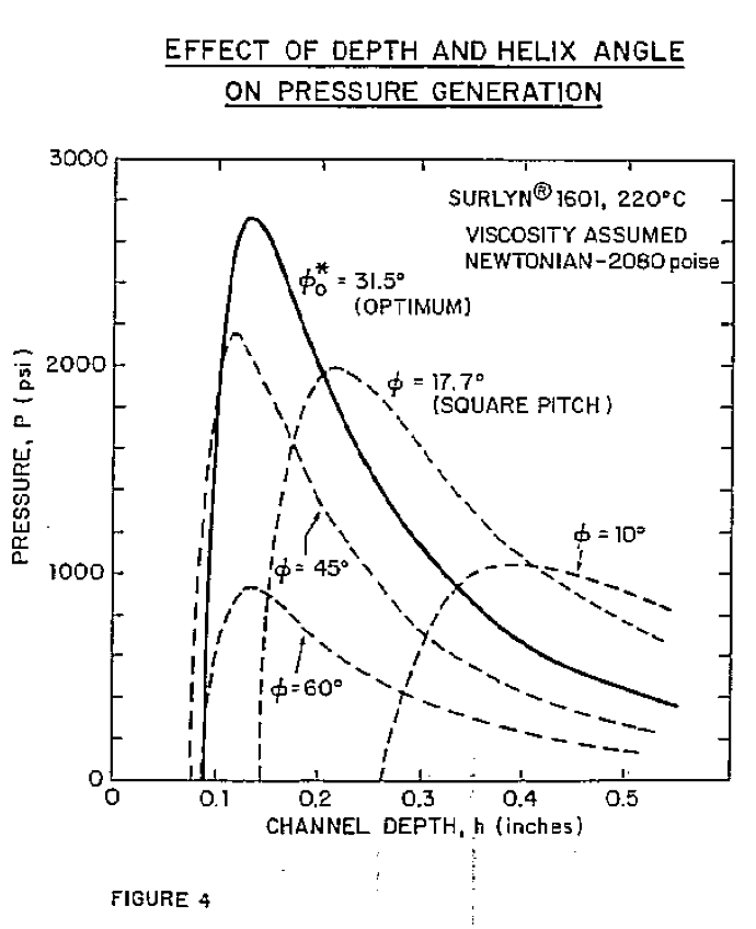
The rheological behavior of surlyn* 1601 is shown in Figure 3. The length of 7.4. diameters was assumed since it results in a convenient and realistic 2,000 psi discharge pressure with an optimized square-pitch screw. A fixed discharge pressure equally well could have been assumed in this case the required length, rather than developed pressure, would be calculated. The total design length of the pumping section typically should exceed the filled length by 30 to 50 percent to accommodate process transient conditions. For various helix angles we can calculate the maximum pressure which can be developed by this screw as a function of the channel depth by repeated application of Equation 7. For the present, the assumption is made that the melt viscosity remains constant at 2,080 poise. This is the viscosity at a shear rate of 86 sec
-1 which exists when the channel depth is optimized at 0.212 inches for a square-pitch screw. This assumption of constant viscosity has important implications and later will be removed. The results of these calculations are shown in Figure 4. The channel depth, h* which produces the maximum pressure for each helix angle can be calculated by use of Equation 1, but it is more informative to examine the complete functional dependency of pressure on channel depth as shown in Figure 4. (Although, for example, a channel depth of 0.212 inches is optimum for a helix angle of 17.7°, the converse is not true, i.e., 17.7° is not the optimum helix angle for a channel depth of 0.212 inches. Application of Equation 4 will show that a helix angle of 21.6° will maximize pressure development if the channel depth is 0.212 inches. The better design logic is to select a helix angle and then optimize around this selection.)
The simultaneously optimized helix angle theta*o and channel depth, h*, obtained by use of Equation 5 and 1 for this example are 31.5" and 0.131 inches, respectively. These result in the maximum pressure generation of 2,718 psi. This can be seen on Figure 4 to be the maximum pressure on the curve representing performance at a helix angle of 31.5°.
Simultaneous optimization thus appears to increase the pressure which can be developed by the screw from 2,000 psi. if a square pitch is used, to 2,718 psi - a 36% gain. This is equivalent to stating that a length of 5.4 diameters with helix angle and depth optimized would do the same job in pressure generation as a pumping section 7.4 diameters long when optimized at a helix angle of 17.7°. This could be an important margin of safety in the "go" or "no-go" performance of the pumping section discussed earlier.
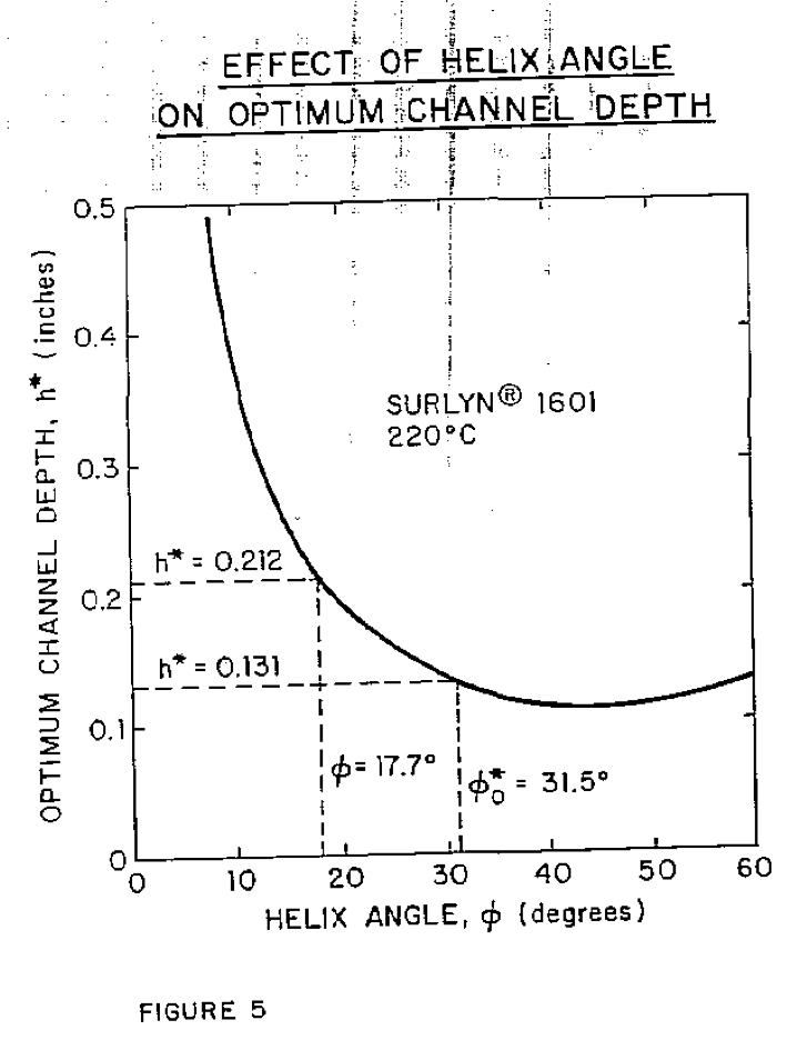
But are these apparent benefits with a 31.5° helix angle and 0.131 channel depth indeed realized? The answer in the case of surlyn* 1601, which is quite non-newtonian, is "no". In Fiqure 5 is plotted the channel depth, h*, from Equation 1 which maximizes the pressure generation for a range of helix angles. This channel depth decreases as the helix angle is increased to 45°. This causes higher shear rates in the channel, lower melt viscosity because of non- newtonian effects, and lower resultant pressure generating capability. The assumption of constant viscosity made earlier must be questioned.
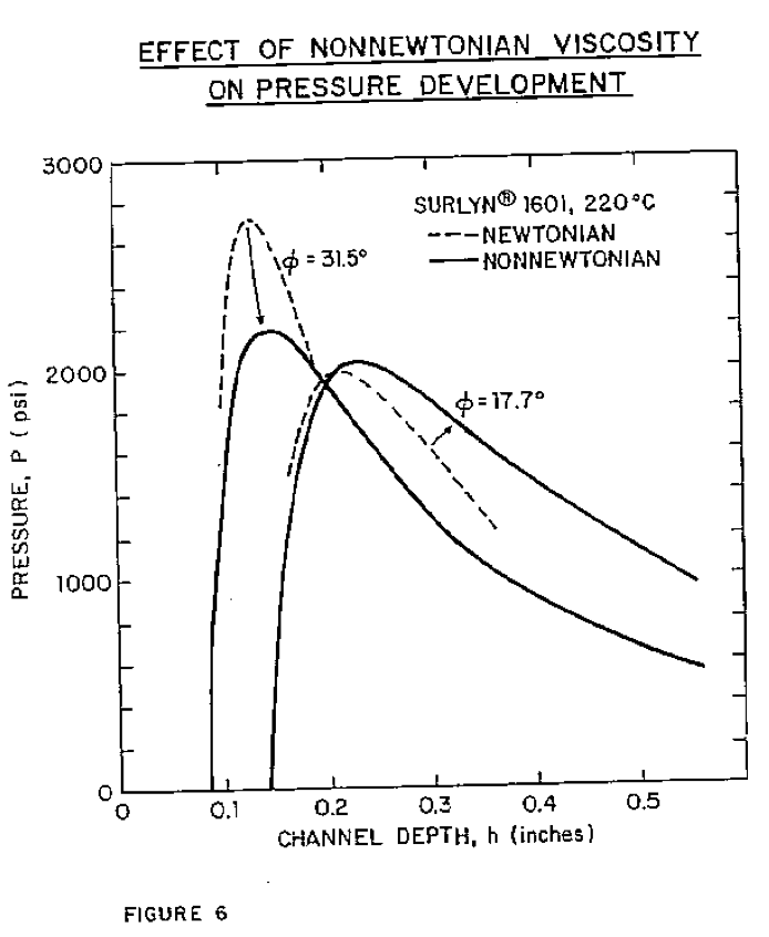
The calculations supporting Figure 4 for helix angles of 17.7° and 31.5" were repeated, but with the non-newtonian viscosity of surlyn* 1601 taken into consideration by the technique developed by Booy (30). The results of this recalculation are shown in Figure 6. The gain in performance potentially available by simultaneously optimizing the helix angle at 31.5° and the channel depth at 0.131* is almost completely nullified by the reduced melt viscosity at the higher shear rate in this shallow channel.
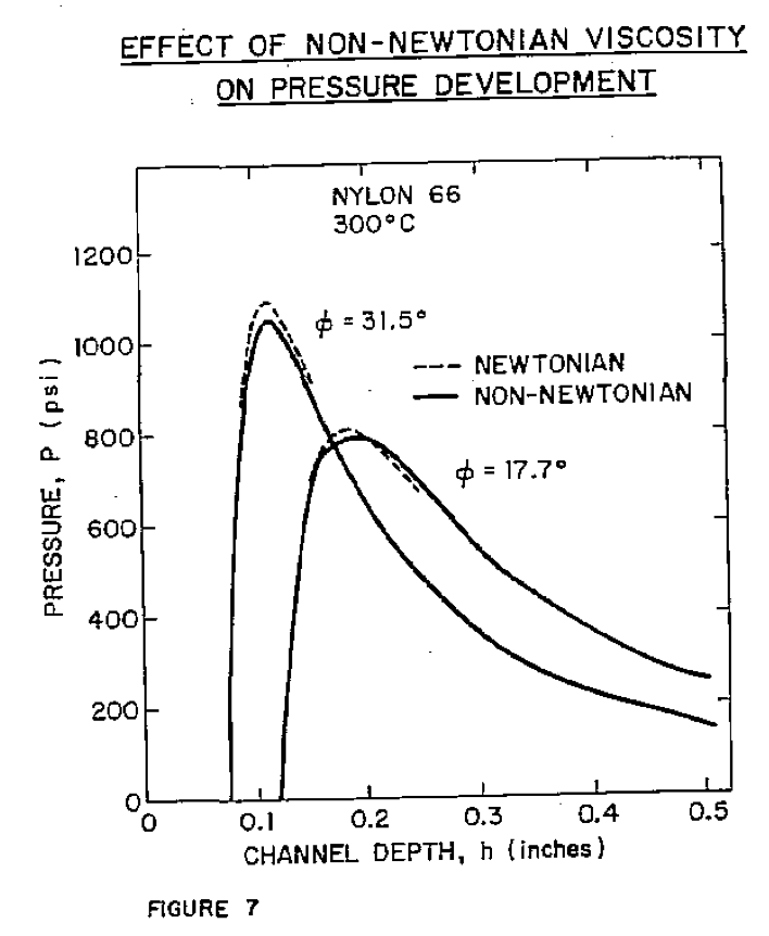
The situation for a polymer which exhibits more nearly newtonian behavior is quite different. To illustrate, calculations analogous to those for Surlyn* 1601 in Figure 6 have been repeated for Zytel° 101 nylon 66. The results are shown in Figure 7. With this more newtonian polymer melt, full optimization of design can produce a 31% gain in maximum pressure development over that of an optimized design having a 17.7° helix angle. This is a substantial performance gain - particularly as judged within the context of the critical nature of the design of the pumping section in an extractor screw.
Optimized Engineering DesignThe most attractive design for the pumping section is one which not only will develop a high pressure, but which also will develop an adequate pressure over a broad range of conditions and resin properties. A pumping section somewhat deeper than the theoretical optimum will not develop the highest possible pressure at design rate, but will develop higher pressures than the theoretical "optimum" screw should actual rates exceed design. Such higher rates could be caused by better-than-expected performance of the melting zone of the two-stage screw or by transient surges. Use of theoretical optima thus must be tempered by engineering judgment.
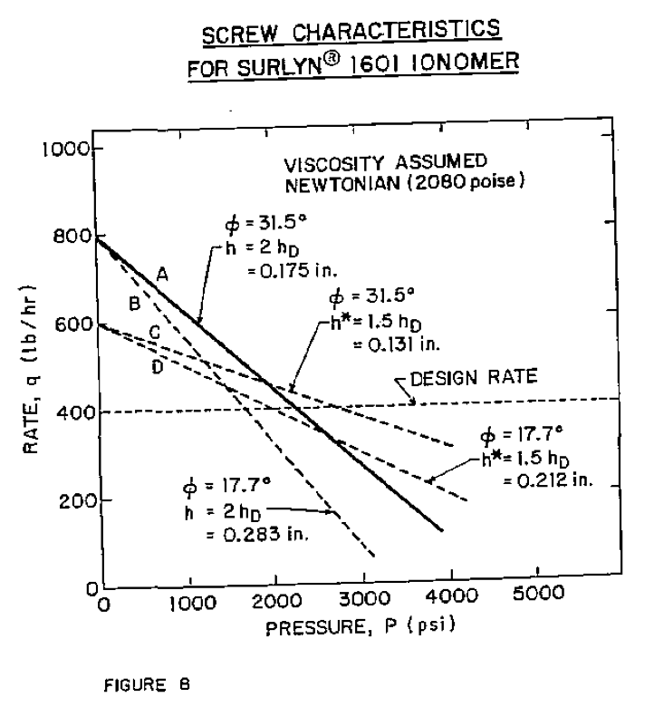
Equation 7 was used to calculate performance of the pumping section for Surlyn* 1601 with a range of helix angles and channel depths bracketing the theoretical optima calculated by Equations 1 and 4 for both newtonian and non-newtonian polymer behavior. Cases showing the more important conclusions were selected for illustration in Figure 8.
The pressure of 2,718 psi at 400 lbs/hr obtainable with screw C having a 31.5° helix angle and channel depth of 0.131" (1.5 h
0) is the maximum obtainable with any combination of helix angle and channel depth. If the rate were to exceed about 500 lbs/hr, however, screw B of a more conventional square-pitch design would have higher pressure-generating capability. Screw A appears to be the best-balanced design. This screw with a helix angle of 31.5° and a channel depth of 0.175* (2 h
p) will produce a higher maximum pressure at 400 lbs/hr than any screw having a 17.7 degree helix: angle while at the sane time retaining an advantage in pressure capability at higher rates. The cases shown in Figure 8 are for newtonian behavior. The effect of non-newtonian fluid behavior is to reduce the difference in performance between the various screws; conclusions remain unchanged.
Use of a pumping section depth equal to 2h
0 rather than an additional advantage, i.e., elimination of the possibly disconcerting situation in which the pumping section is shallower than the upstream metering section. To illustrate - the metering section depth in the example screw would be about 0.142 inches if the square Pitch helix angle of 17.7° were used in the metering section. With a 31,5° helix angle in the pumping section the theoretical optimum pumping section depth is 0.131 inches (1.5h calculated at theta = 31.5°, not 17.7°) - less than the 0.142 inch depth of the upstream metering section. The pumping section depth would be 0.175 inches - greater than the metering depth - if the "engineering optimum" design recommended earlier were used
where h = 2h
D.
ConclusionThe results of this study support several conclusions on design of pumping sections for two-stage screws:
- Use of the industry-accepted square-pitch screw having a helix angle of 11.7° is a cost-effective design with moderate pressure-generating capability relative to pressure attainable through optimization. But -
- Pressure-development capability of the pumping section in a two-stage extractor screw is critical to satisfactory performance. In this situation, an optimized design incorporating a "non-square" pitch screw is justified and recommended for the pumping section.
- The optimum channel depth for development of maximum pressure at any helix angle is 1.5 times the drag-flew depth at the same helix angle. A wider range of acceptable performance is obtained, however, if the depth is increased to 2.0 times this drag-flow depth.
- If helix angle is optimized simultaneously with channel depth, the optimum angle will be close to 30° for screws in which the ratio of flight area to total circumferential area is small.
In summary, it appears that an attractive design for the pumping section is one which incorporates a helix angle of about 30° (the helix angle may be calculated from Equation 5 and a channel depth of twice the drag-flow depth at this same helix angle. Gains in pressure-development capability of the pumping section achievable through such optimization will range from about 5 to 30° -- the specific gain being determined by the degree of non-newtonian behavior of the Polymer melt and by the extent to which the screw design departs from the theoretical optimum in order to achieve a broader range of operability.
Nomenclature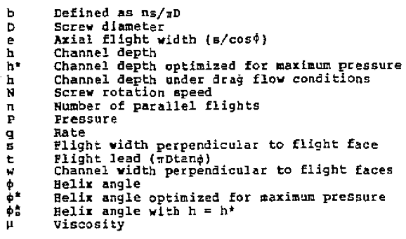
1. R. E. Nunn, 5th SPE ANTEC, 1-19 (1980)
2. M. Bess and K. Eise, SPE Tech. Papers, 23, 460-3 (1977)
3. R. E. Hunn, Plast. Eng., 36, No. 2, 35-39 (Feb. 1980)
4. Z. Tadmor, P. Bold, and L. Valsamis, Plast. Eng., 35, No. 12, 34-38 (Dec. 1979)
5. G. Martin, British Patent 2012203, assigned to Berstorff Company
6. A. Rutherford, Plast., S. Africa, 8, No. 5, 39-44 {Feb. 1979)
7. J. M. McKelvey and S. Steingiser, Plast. Eng., 34, No. 6, 45-49 (June 1978)
8. Anon., Mod. Plast. Int., 7, No. 9, 8-11, (Sept. 1977)
9. T. G. Bishop and G. A. Kruder, Mod. Plast. Int., 7, No. 4, 51-59 (April 1977)
10. R. J. Nichols, G. A. Kruder, and R. E. Ridenour, SPE Tech Papers, 22, 361-3 (1916)
11. R. Decapite and C. S. Gudermuth, Plast. Eng., 32, No. 1, 37-39 (Jan. 1976)
12. N. J. Brozenick and G. A. Kruder, SPE Tech Papers, 20, 466-8 (1974)
13. C. S. Gutermuth and T. G. Bishop, Plast. Eng., 30, No. 5, 56-50 (May 1974)
14. D. Gras and K. Eise, SPE Tech. Papers, 20, 386-9 (1975)
15. D. Gras, SPE Tech. Papers, 19, 263-8 (1973)
16. I. Ronzoni, A. Casale, and G. DeMarosi, SPE Jor., 27, No. 10, 76-81 (Oct. 1971)
17. W. Backhoff, R. Van Hooren, and P. Johannaber, Kunststoffe, 67, No. 6, 1-13 (June 1977)
18. R. Petsch and S. Wintergerst, Kunstoffe, 66, No. 7, 4-5 (July 1976)
19. G. Latinen, ACS Advances in Chem. Series, 34, 235 (1962)
20. R. W. Coughlin and G. P. Canevari, AIChE Jor., 15, No. 4, 560-4 (July 1969)
21. G. W. Roberts, AIChE Jor., 16, No. 5, 878-882, (Sept. 1970)
22. J. A. Biesenberger, Poly. Eng. & Sci., 20, No. 15, 1015-22 (Oct. 1980)
23. P.H. Squires, SPE Jor., 14, No. 5, 24 (May 1958)
24. J. F. Carley, R. S. Mallouk, and J.M. McKelvey, Ind. Eng. Chem., 45, No. 55 974-8 (May 1953)
25. C. J. Rauwendaal, SPE Tech Papers, 26, 110-113 (1980)
26. J. M. McKelvey, "Polymer Processing", 255, J. Wiley & Sons, (1962)
27. P. H. Squires, Chpt. 4 of "Processing of Thermoplastic Materials", pg 211, ed. E. C. Bernhardt, Reinhold (1959)
28. Z. Tadmor and I. Klein, "Engineering Principles of Plasticating Extrusion", pg 223, Van Nostrand Reinhold (1970)
29. S. Middleman, "fundamentals of Polymer Processing", pg. 137, McGraw-Hill (1977)
30. M. L. Booy, Poly. Eng. & Sci., 21, No. 2, 93-9 (Feb. 1981)
AppendixIn order to obtain the most generalized expressions for optimum depth and helix angle, the existence of one or more flights of finite width has been incorporated into the following deviations.
I. Optimum Channel DepthThe flat-plate two-dimensional model for flow in a screw pump leads to an expression for rate (Ref. 27, pg. 174) that may be written as
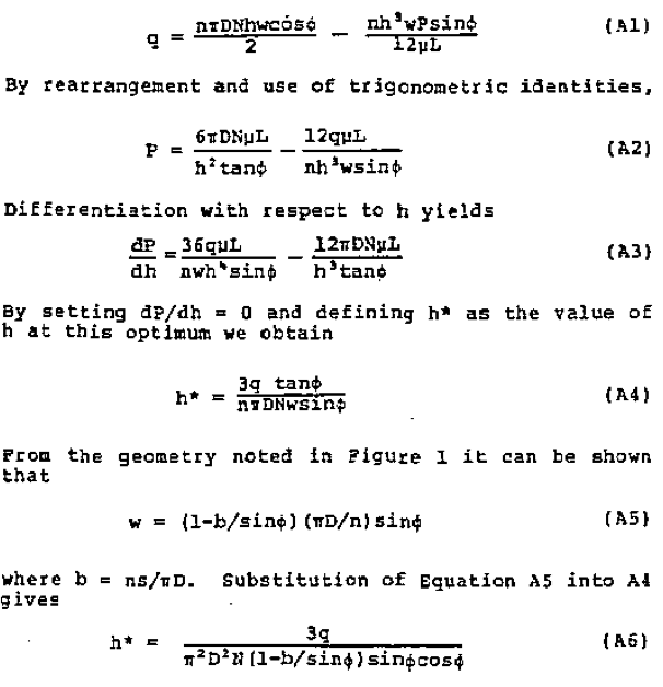
Equation A6 was found more convenient than the equivalent Equation A4 for use in the computer programs supporting this study.
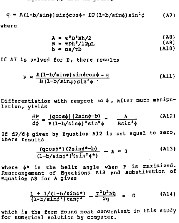
II. Optimum Helix AngleThe flight width, s, measured perpendicular to the flight faces will be considered invariant in developing an expression for optimum helix angle. Substitution of Equation A5 into A1 yields
Return to
Best Papers.
