Universal Melt Temperature Diagram
Stephen J. Derezinski, Extruder Tech, Inc., Penfield, NY 14526 Abstract
The Universal Melt Temperature Diagram (UMTD)
provides the developing melt temperature vs. length of an
extruder based on four unique dimensionless groups.
Factors included in the four groups are:
• the dependence of melt viscosity on shear and
temperature,
• resin thermal properties,
• screw geometry, and
• process conditions.
Melt temperature vs. extruder length is provided in a
succinct format that vividly illustrates the melt temperature
development process.
Introduction
In the melt section of the extruder, the temperature
of the molten polymer develops as it flows to the exit. At
the exit, the temperature is defined as the product
temperature, and it has a bulk average value and a
distribution. With the UMTD accurate analysis of the melt
temperature development and product temperature can be
made to assess performance. This work is an extension of
previous work for melt-temperature dimensionless functions
[1,2] and melt-zone heat transfer coefficients [2-6]. The
contributions of screw design, resin properties, and process
conditions can be easily analyzed with this comprehensive
diagram.
A few of the factors that can be investigated about
the process are:
• Is there excessive residence time?
• Is the temperature uniformity near optimum?
• Are the barrel zone temperatures set properly?
It will be shown how the UMTD, a single diagram of
temperature vs. length, universally illustrates these conditions
of importance to good product quality.
Basics Assumptions of the UMTD
The UMTD is based on the conservation of energy for the
resin melt flow. These basic governing equations (See
Appendix 1) equate the change in energy of the resin melt to
the sum of viscous shear energy provided by the screw and
of heat transfer with the barrel. Basic assumptions are:
• The change in energy is assumed to be proportional to
the product of the resin melt specific heat and melt
temperature change.
• The viscosity of the resin melt is assumed to follow the
Carreau-Yasuda model for shear strain rate. See
Appendix 2.
• The viscosity (Appendix 2) is assumed to follow an
exponential function of temperature. The reference
point is the viscosity modulus at the barrel wall
temperature which ties the exponential function closely
to the viscosity vs. temperature data curve.
• Heat transfer with the barrel is assumed to be a function
of the heat transfer coefficient between the melt and the
barrel, which is known to be a function of flight
clearance and screw speed [2-6].
• A known fixed screw-geometry consists of a helical
channel formed by a flight with a small clearance.
• Screw speed, fixed barrel wall temperature, and flow
rate are known.
• Thermal properties of the resin melt are known
constants.
• Thermally steady-state equilibrium and an adiabatic
screw are assumed.
The melt section length of the extruder is divided into
“melt zones”. Melt zones are defined as any length of the
melt section that has constant barrel zone temperature and
fixed screw geometry. A change in either one of these
constitutes the beginning of a new melt zone.
Unique Dimensionless Groups
The UMTD depends upon a set of four
dimensionless groups for its universality as follows:
1. θ, Temperature
2. χ, Axial Position
3. N
h, Barrel Heat Transfer Coefficient
4. N
CY, Carreau-Yasuda Shear Strain
All four of the dimensionless groups are mathematically
defined in Appendix 1 along with the governing equation.
Each group is defined as uniquely having a variable
of the process as a factor and so named. For example, the
first group is the temperature number, because it is the only
group of the set that has temperature explicitly as a factor
(equation 5). The temperature number is on the ordinate of
the UMTD to solely represent average melt temperature.
Similarly, the abscissa is represented by the uniquely defined
axial position number, equation 6. Therefore, the UMTD
axes are proportional to temperature vs. extruder axial
position so as to appear in form and shape to data for
temperature vs. axial position. Therefore, the UMTD is
easily related to actual machine operation and interpretation.
The UMTD will be shown to have two domains.
The first domain represents conditions for heating the melt,
and the second for cooling the melt. Conditions for heating
the melt are most common for plastic extrusion. They will
always occur when the melt temperature entering a melt
zone is less than the fully developed melt temperature for
that melt zone.
UMTD (Melt Heating Domain)
Figure 1 shows the UMTD for the melt heating
domain. Parametric curves based on the ratio of barrel heat
transfer coefficient number, Nh, to the shear-strain number,
NCY, provide the average resin melt temperature number, θ,
vs. extruder axial position number, χ. The heat transfer
number is unique to heat transfer coefficient, and the shearstrain
number is based on the Carreau-Yasuda equation for
viscosity. See Appendix 1.
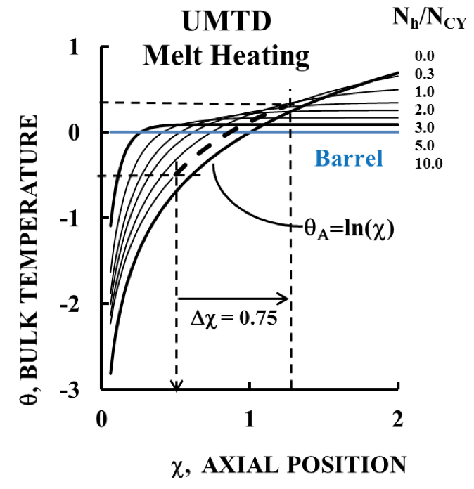
Figure 1. The basic UMTD for Melt Heating. Units are all dimensionless. An adiabatic barrel solution, θA, is shown as a limiting condition. An example for a single melt zone is shown by the dashed lines.
The beginning of a melt zone, χ
0, is defined by the
melt temperature at the inlet to the zone, θ
0, and the
prevailing ratio of heat transfer number and shear strain
number, N
h/N
CY. For the example shown in Figure 1, a melt
zone with a value of θ
0 of -0.5 and a value of N
h/N
CY of 0.3
gives an inlet position of χ
0 = 0.5 for this melt zone.
The end of the melt zone then occurs when the
barrel zone temperature or the screw geometry is changed.
In Figure 1 a change in axial position, ∆χ = 0.75, is shown
that is calculated based on the actual length, L, of the melt
zone. This change in axial position, ∆χ, is then added to the
initial position, χ
0, to determine the position of the end of the melt zone, χ
L, on the UMTD. Figure 1 shows for the
example that a change in axial position of ∆χ = 0.75 would
make the end of the melt zone, χ
L, occur at an axial position
of 0.5 + 0.75 = 1.25. The curve along N
h/N
CY = 0.3 would
be the path of the melt temperature development between
axial positions 0.5 and 1.25. The diagram shows the
approximate exit temperature number is θ
L = 0.3.
Fully Developed Melt Temperature
Figure 1 shows that the temperature stabilizes to a
constant value at some a point as axial position is increased.
Above this point any additional length of the melt zone will
not change the melt temperature. Therefore, this stable
temperature is fully developed. For melt heating it
represents a maximum value for the melt zone.
Figure 2 gives the axial position of the beginning
of fully developed melt temperature as a function of heat
transfer and shear strain numbers. The practical importance
of this is that undue residence time will be added to the melt
at greater axial length. Longer residence time is often
associated with poor product quality, such as discoloring.
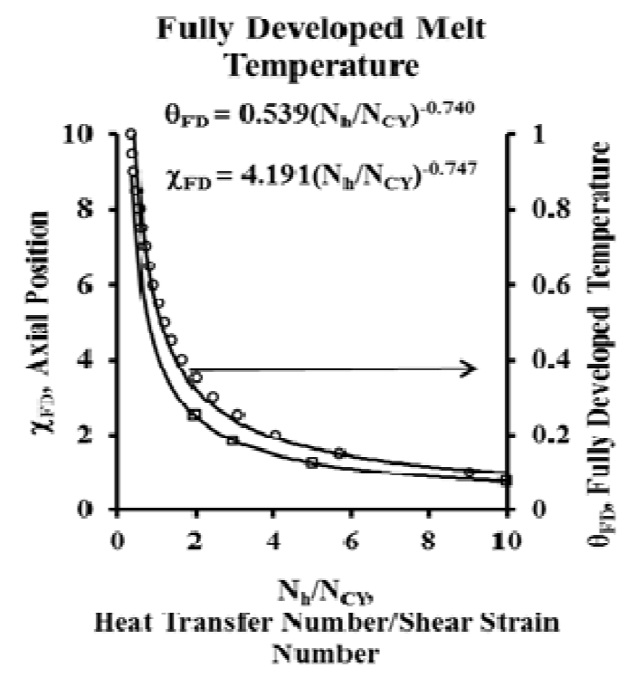
Figure 2. Axial Position Number at which Fully Developed Melt Temperature Begins and Fully Developed Temperature. They are a funtion of only heat transfer and shear strain numbers.
The fully developed temperature shown on the right
axis of Figure 2 is a key value for each melt zone. The
fully developed temperature will not change once this axial
position given by Figure 2 is reached without changing
process parameters or entering a new melt zone.
The hyperbolic shape of the curves of
Figure 2 illustrates that heat transfer coefficient and shear
strain have a point of diminishing returns as the heat transfer
is increased and/or shear strain is decreased. That is, at high
values of N
h/N
CY, change in it is less significant to temperature change. This would occur for high heat transfer
coefficient and/or low viscosity and shear. These conditions
are not typically found in plasticating extruders which have
viscous flow with moderate or low heat transfer coefficients.
The fully developed temperature does occur in
large metering extruders that are designed to only pump melt
at contant temperature with the purpose of stabilizeing flow
disturbances. The screw is normally of fixed channel
dimensions and helix angle. Heat must be removed over the
entire length of the extruder to maintain the constant melt
temperature, and that energy is provided by the motor.
UMTD (Melt Heating) Temperature Limits
Figure 1 clearly shows that there are an upper limit
to the melt temperature and a lower limit to the melt
temperature. Figure 3 shows how melt temperatures will fall
between these two limits for this domain of increasing the
melt temperature. If they do not, then one or more of the
assumptions of the UMTD is violated (such as steady state
conditions) or the data are incorrect. This makes the UMTD
a useful diagnostic tool.
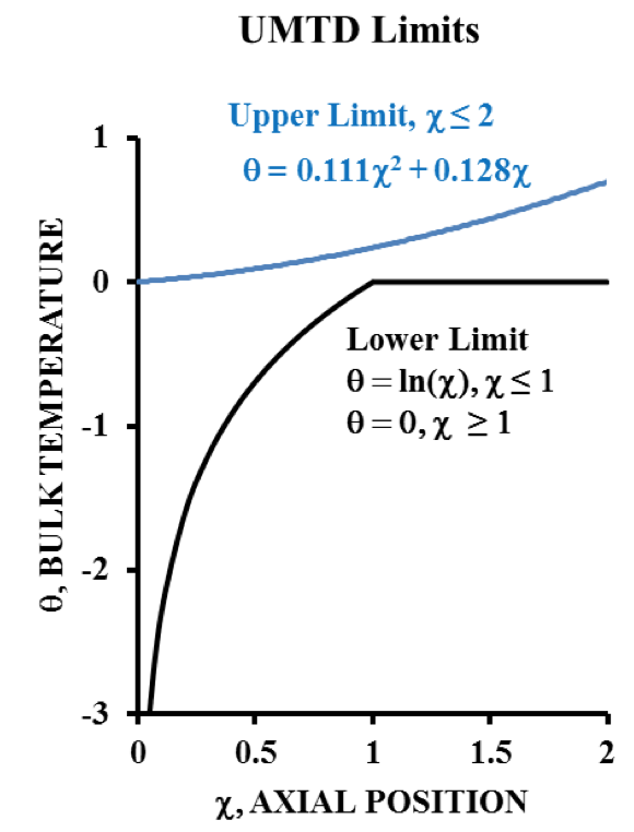
Figure 3. Upper and Lower Limits of Melt Temperature Heating
In Figure 1, the temperature function for an
adiabatic barrel is shown as θ
Α = ln(χ). This is an analytical
solution to the governing energy balance, and it represents
the limit of a fictitious adiabatic barrel (heat transfer
coefficient = 0). All of the other curves are obtained through
a finite difference solution to the governing equation, and
they represent conditions that could actually occur. In
Figure 3, the adiabatic solution provides a lower
mathematical limit to the melt temperature for position
value, χ, less than one.
Also, note in Figure 3 that there is a “narrows”
between the upper and lower limit at χ = 1. The significance
is that at this point the variation in melt temperature is
minimal. The consequence is that the melt temperature is
least sensitive to variations of any of the other variables for
χ at or near a value of 1. This would be a good condition to
occur at the end of the extruder to minimize variations in
product temperature uniformity. Figure 3 also shows that
above a value of χ= 1 the melt temperature will always be
hotter than the barrel wall temperature (θ = 0).
UMTD (Melt Cooling Domain)
Figure 4 shows the second domain, UMTD Melt
Cooling, for temperatures always decreasing. This occurs
when the melt temperature entering the melt zone is greater
than the fully developed temperature given by Figure 2 since
the fully developed values of temperature for the melt
cooling are the same as for melt heating. Ultimately the
fully developed temperature will be reached if the melt zone
has enough length to reach axial position value given by
Figure 2.
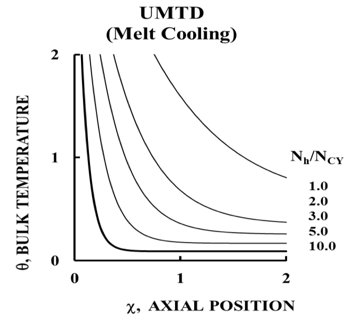
Figure 4. Melt Cooling The temperature of the melt entering the melt zone is greater value than the prevailing fully developed melt temperature.
Cooling of the melt is not typically done in plastic
extrusion since this would be needed as a result of
overheating the melt. Overheating is avoided as it would
lead to degradation of the resin. Cooling the melt stream is
also very inefficient because viscous heating requires
substantially colder barrel zone temperature, and this would
lead to excessive temperature gradients and possible resin
freeze-out on the barrel walls. Melt zones can be established
so as to avoid needless melt cooling with the aid of the
UMTD.
Total UMTD
Figure 5 shows the full UMTD consisting of both
heating and cooling domains for comparison. The cooling
domain (upper in blue) is noticeably inefficient as compared
to the heating domain (lower in black). Viscous heating will
hinder cooling the melt in the cooling mode, but it aids
heating of the melt in the heating mode. This makes cooling
of the melt inefficient compared to heating of the melt, and
this is quantifiably evident by the UMTD.
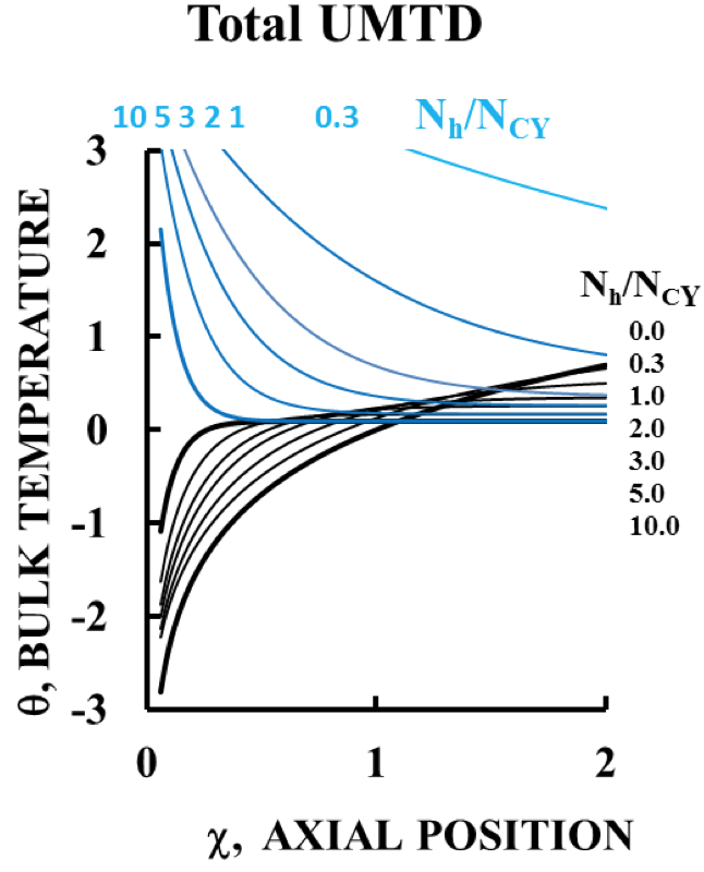
Figure 5. The Complete UMTD Melt heating and melt cooling shown for comparison.
Temperature Distribution
The temperature distribution of the melt between
the barrel and the screw can be calculated based on the data
for the bulk temperature used by the UMTD. Known values
of
1. bulk temperature,
2. barrel wall temperature,
3. heat flux at the barrel wall, and
4. the assumption of an adiabatic screw
provide four independent parameters used to calculate the
temperature distribution of the melt with a cubic function.
See Appendix 3 for details.
Data for the exit melt temperature distribution for a
31.75 mm, 16/1 L/D extruder were measured [7] with a
thermocouple bridge spanning a 25.4-mm diameter exit pipe.
The resin was LDPE, and Figure 6 shows the data [7]. Also
shown is the exit melt temperature cubic profile calculated
from the UMTD analysis as described above, and good
agreement is noted. The prediction compares well with an
iterative approach used later for the same test setup [8].
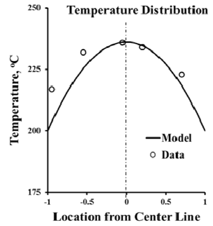
Figure 6. Temperature Distribution for LDPE Model based on UMTD analysis of bulk temperature distribution.
The cubic function used here to model the
temperature profile will demonstrate a known variety of melt
temperature profiles. The UMTD predicts the average
temperature, but for a given average temperature dramatic
differences can occur in the melt temperature profile
predicted by the cubic function.
For the above example a hypothetical doubling of
the viscosity modulus, η
w, can be studied for its effect on the
temperature profile. To maintain dimensionless similarity,
the heat transfer coefficient, h, would be doubled (see
equation 8, Appendix 1) and the melt section length, L,
would be halved (see equation 7, Appendix 1). The same
values for the dimensionless groups result in the same
predicted average temperature. However, the exit
temperature profile as predicted by the cubic function used
here is dramatically different. Figure 7 shows the
temperature profile to be an “M” shaped profile [9] for this
hypothetical case. Other profiles [8,10], such as “U” shaped
and “inverted M” or “moustache” profiles all result with the
cubic function when proper conditions exist.
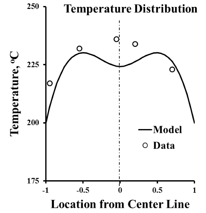
Figure 7. An “M” Shaped Profile The average product temperature for the model is the same as for the data.
The practical significance is that an average product
temperature is subject to a large variety of exit temperature
profiles. Using the UMTD to model the average
temperature leads to calculation of the temperature profile
with the cubic function. A large thermal profile difference
in two processes can be identified even though they have the
same average product temperature.
It is also notable that the melt temperature
distribution so calculated is a constant (uniform) for values
of axial dimension, χ, where θ=0. Therefore, thermal
uniformity is optimized for these values of the axial position.
Summary
The UMTD (See Appendix 4 for enlarged version)
is a single diagram created to model the melt temperature
development in a single screw extruder in detail. Only four
dimensionless groups are needed to include viscosity
dependence on shear and temperature, process conditions,
screw design, and resin melt thermal properties. Each group
is singly associated with a single process variable to make
the results easily and meaningfully interpreted in terms of an
actual melt temperature profile.
Conclusions
1. The Universal Melt Temperature Diagram (UMTD)
graphically shows the melt temperature changes as
the melt flows to the exit. Various characteristics of
the curves are given that define what is needed for
good processing.
2. Finite temperature limits are established for the melt
with the UMTD.
3. The UMTD shows the melt can be either heated or
cooled with an extruder.
4. Cooling of the melt with an extruder is demonstrated
to be very inefficient by the UMTD.
5. Conditions for optimum product temperature
uniformity are clearly defined by the UMTD.
6. Data show melt temperature distribution can be
accurately calculated with the results of the UMTD.
7. Conditions for fully developed melt temperature are
identified.
Nomenclature
a Yasuda exponential term for shear strain
B exponential factor for melt viscosity vs. temperature
C
p Melt specific heat
h Heat transfer coefficient, melt to barrel
H Channel depth (constant)
H
R Ratio of channel depth to flight clearance
k Thermal conductivity of melt
L Melt section length
n Exponential term for shear strain
N
CY Carreau-Yasuda dimensionless strain group
N
h Heat transfer dimensionless group
T Temperature
T Bulk temperature
T
W Temperature of barrel wall
v Average melt velocity, axial direction
V Screw surface speed
Vo
c Channel volume fraction
Vo
f Flight volume fraction
x Location between barrel wall and screw channel
z Axial position
γ Shear rate
∆χ Melt section dimensionless length
η Viscosity
η
W Viscosity modulus at barrel wall temperature data
θ Dimensionless temperature
θ
A Temperature for an adiabatic barrel
θ
FD Fully developed temperature
θ
L Axial temperature at of end of melt zone
θ
0 Temperature at start of melt zone
λ Carreau factor
ρ Melt density
χ Dimensionless axial position
χ
L Axial position at end of melt zone
χ
0 Axial position at beginning of melt zone
References
1. S. J. Derezinski, “Dimensionless Curves for Extruder
Melt Temperature and Flow”, Conference
Proceedings, ANTEC ’87, Society of Plastic
Engineers, 1987, pp. 98-102.
2. S. J. Derezinski, “Heat Transfer Coefficients in
Extruder Melt Sections”, Conference Proceedings,
ANTEC ’96, Society of Plastic Engineers, 1996, pp.
417-421
3. Jepson, C.H., “Future Extrusion Studies”,
Industrial and Engineering Chemistry, Vol. 45, No.
5, May 1953, pp. 992-993.
4. McCabe, Warren, and J. C. Smith, Unit Operations
of Chemical Engineering, Third Edition, McGrawHill,
Inc., 1976, pp.378-280.
5. Tadmor, Zehev, and I. Klein, Engineering
Principles of Plastic Extrusion, Van Nostrand
Reinhold Company, 1970, p. 259.
6. Rauwendaal, C., “The Effect of Flight Clearance on
Extruder Performance”, Society of Plastic
Engineers Technical Papers Volume XXV, ANTEC
89, 1989, pp. 108-110.
7. McCullough, T. W. and R. T. Hilton, “Predicting
Melt Temperatures Using an Adjustable, Exposed
Tip Thermocouple”, Conference Proceedings,
ANTEC ’92, Society of Plastic Engineers, 1992, pp.
927-930.
8. McCullough, T. W. and M. A. Spalding,
“Predicting Actual Temperature Distributions in a
Polymer Stream Using an Adjustable, Exposed-Tip
Thermocouple Assembly”, Conference
Proceedings, ANTEC ’96, Society of Plastic
Engineers, 1996, pp. 412-416.
9. Stevens, M. J. and J. A. Covas, Extruder Principles
and Operation, Chapman and Hall, Second Edition,
1995, pp. 358-359.
10. Chung, Chan I., Extrusion of Polymers, Theory and
Practice, Carl Hanser Verlag, Munich 2000, p. 32.
Appendix 1
Dimensionless Variables
Dimensionless
Energy Equation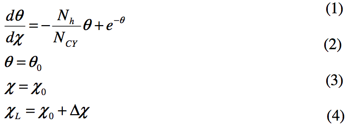
Dimensionless
Temperature
Dimensionless
Axial Position 
Dimensionless
Melt Zone Length 
Dimensionless
Heat Transfer Coefficient
Dimensionless
Shear Strain Function
Adiabatic Barrel Condition, set N
h = 0 in equation 1.

Appendix 2
Viscosity
The viscosity is assumed to follow the Carreau-Yasuda
Equation for shear combined with an exponential function
for temperature as follows:

where the value of the viscosity modulus ηw, at the known
barrel wall temperature, T
w, is obtained from actual viscosity
vs. temperature data. The value of exponential constant, B,
can also be adjusted according to the wall temperature or
shear rate.
Appendix 3
Cubic Temperature Distribution
The four factors that result from the temperature analysis are
used to estimate the melt temperature distribution as follows.
The distribution is assumed to follow a cubic function as

Bulk melt temperature is known, so

Barrel wall temperature (x=0) is known, so

Heat flux at the barrel wall (x=0) is known, so

An adiabatic screw is assumed (x=H), so

Equations 14-17 are solved for the 4 coefficients of the cubic
equation 13 (a, b, c, and d) to give the temperature profile.
Appendix 4
Enlarged UMTD 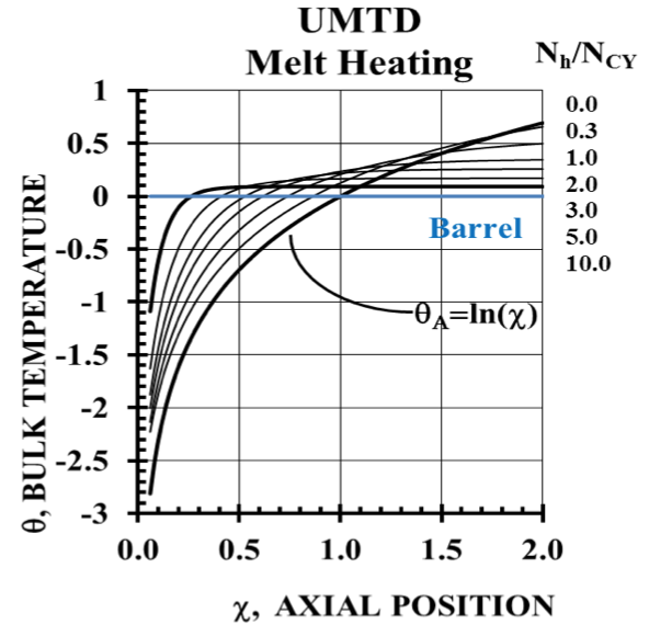
Key Words
Temperature, melt, metering, pumping, model, analysis, plastic, resin, flow, extruder, single-screw
Return to
Paper of the Month.