Understanding and Quantification of Die Drool Phenomenon During Polypropylene Extrusion Process
M. Zatloukal
1, W. Sambaer
1, A. Libotte
21 - Polymer Centre, Faculty of Technology, Tomas Bata University in Zlín, Zlín, Czech Republic
2 - INEOS Polyolefins, Brussels, Belgium
Abstract
In this work, die build-up phenomenon has been investigated theoretically, by using FEM analysis, as well as experimentally for polypropylene resins which are commonly used in the biaxial oriented film production. It has been demonstrated that the negative pressure at the die exit region is correable with die drool phenomenon in this case.
Introduction
Die drool (also called as plate-out, die build up, die drip or die peel) is a phenomenon occurring in melt extrusion of polyolefins, PVC, and filled polymers, which manifests itself as an undesirable build-up of material, normally on the lip or open face of extrusion dies (1-4). In commercial extrusion processes, die deposit can have a significant influence on the productivity, as it requires shutting down the processing line periodically to clean the die. Furthermore, die deposit can also affect the quality of the extruded product. Recently, it has been suggested that the negative pressure occuring at the end of the die can be used to explain die drool phenomenon occuring in mLLDPE extrusion process (3-4). Interesting question is whether the negative pressure theory can also be applied for other polymers. Therefore in this work, the die drool phenomenon has been investigated for polypropylene extrusion experimentaly, through digital image analysis, as well as theoretically by using FEM from the negative pressure point of view.
Introduction
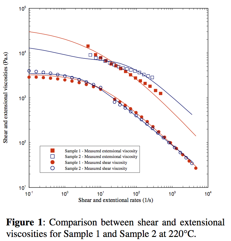
Materials In this work, two polypropylenes (see Table 1) widely used as skin layer in the biaxial oriented film production have been chosen (their notation is Sample 1 and Sample 2 in this work). The main difference between the investigated polypropylenes is the fact that Sample 1 does not contain the Polymer Processing Aids (PPA) whereas the Sample 2 contains PPA. The shear and extensional viscosities of both investigated samples were determined by using Rosand RH7-2 twin bore capillary rheometer and they are provided in Figure 1 for the reference temperature 220
oC.
Experimental set-up for the die drool measurements
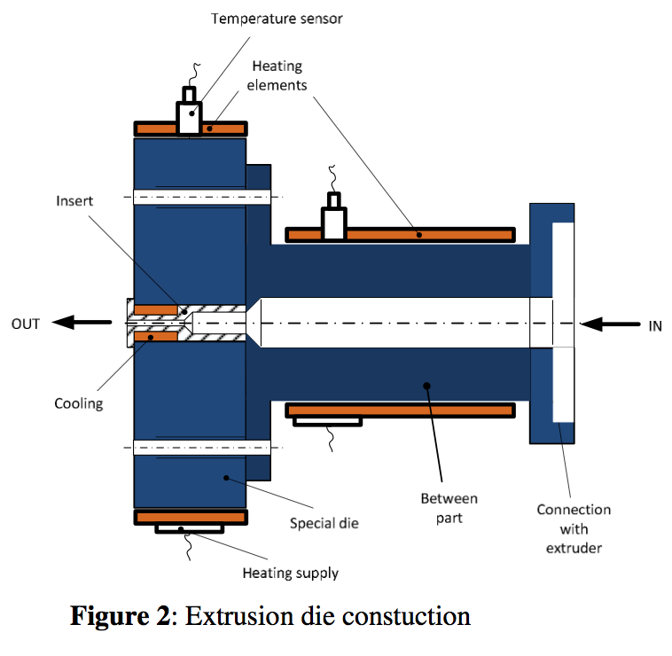
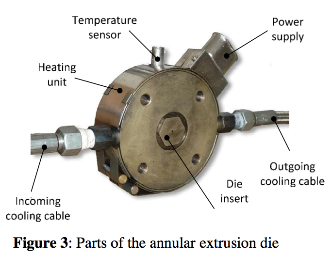
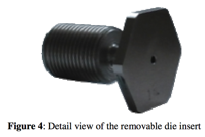
The laboratory measurements were performed on 19 mm conventional Brabender single-screw extruder with a length L = 25D equipped by a specially developed annular extrusion die (Figures 2-4). The extrusion sections (from the hopper to the die) were heated to the following temperatures: T
1 = 80
oC, T
2 = 200
oC, T
3 = 240
oC, T
4 = 260
oC and the annular tube between extruder and annular die was heated to the temperature T
5 = 260
oC. The die wall temperature was 200
oC and the die exit wall was cooled down to 77
oC with the help of cooling medium channel. Mass flow rate for both samples were kept about 0.35 kg/h.
Digital image analysis of the die build-up phenomenon
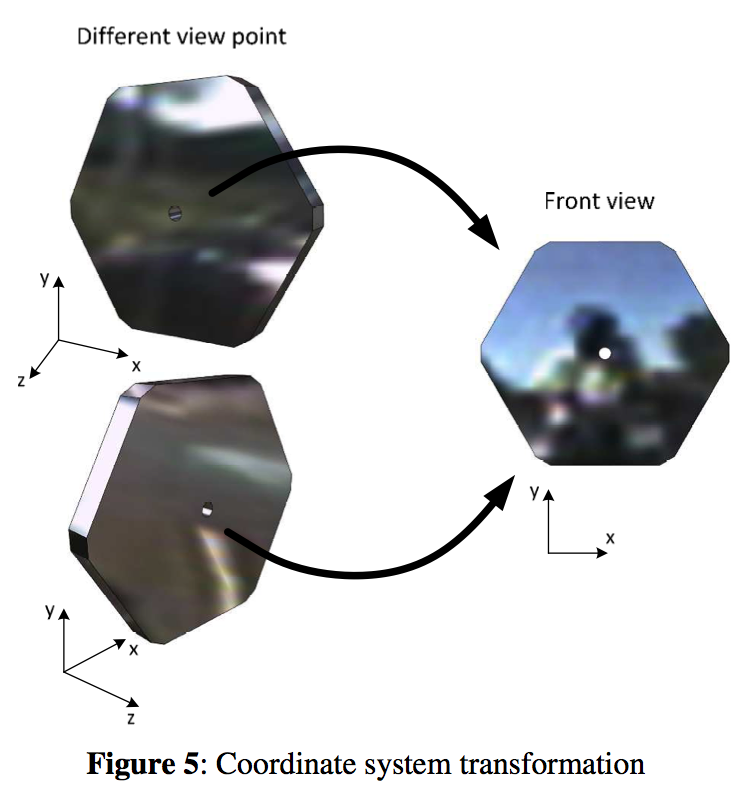
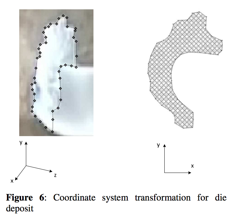
Digital image analysis for die deposit time evolution for both tested samples has been performed simultaneously from two different front angles by using two different instruments. In more detail, digital photo camera (Panasonic Lumix FX12, resolution 7M pixels, shot interval 1 min.) and analog video camera (Sony Handycam, resolution 2.8M pixels, frame rate 25 fps) located at right die side and at the left die side, respectively, were utilized (see Figure 5).To measure the die deposit amount in a good way it was necessary to convert the 3D perspective of the two viewpoints to a 2D front view i.e. it was necessary to convert the 3D coordinate system to a 2D coordinate system as shown in Figure 5. For this purpose, ‘Didger® 3.03’ software has been used. The Figure 6 shows in what way the die deposit amount (in terms of die deposit surface area) for particular case (die deposit for Sample 2 after 10 minutes) is quantified by the use of above described transformation technique. In this way, all videos and photo shots were analyzed and the relative Die Deposit Amount (DDA) was determined as the die deposit surface area divided by the capillary die surface area. It should be mentioned that taking the die deposit surface as the die deposit intensity measure is acceptable only if die deposit predominantly occurs in one plane and not so much in the thickness direction, i.e. only at the die build-up onset.
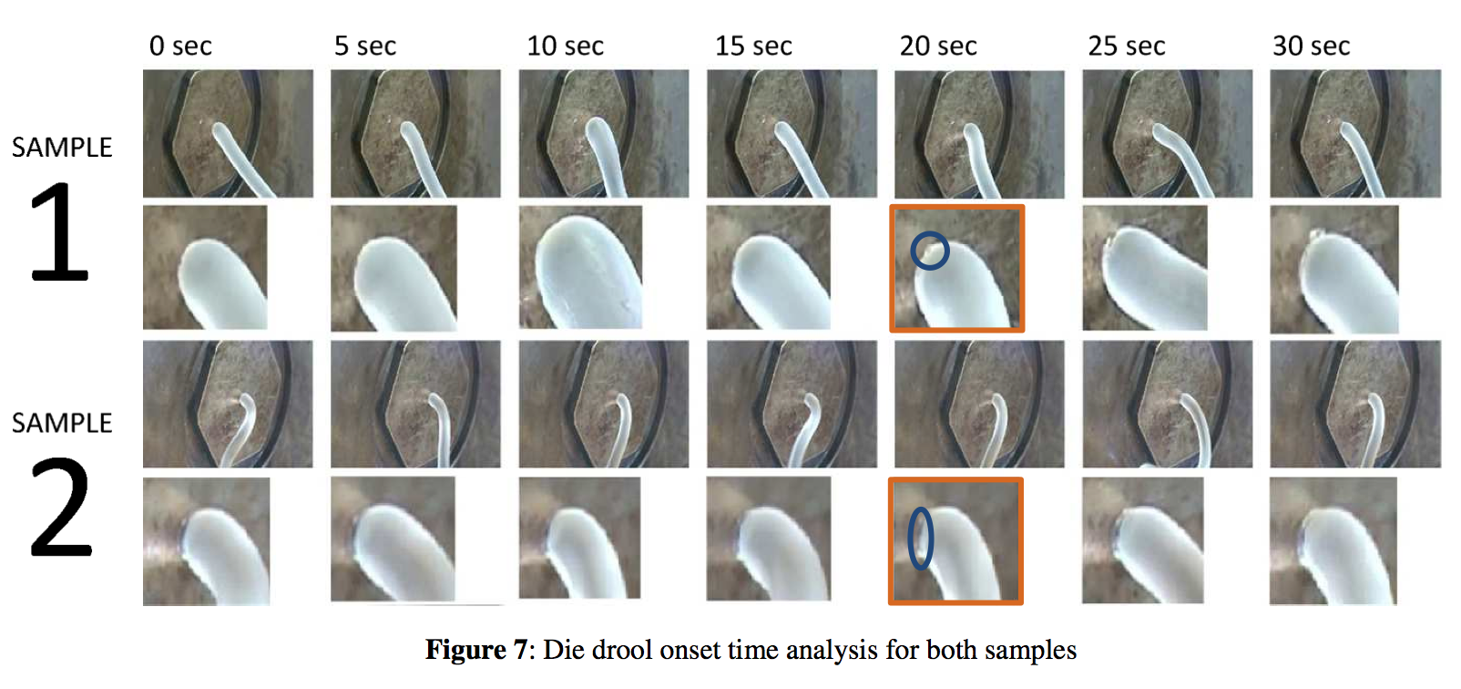
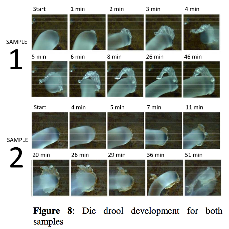
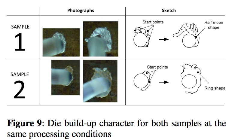
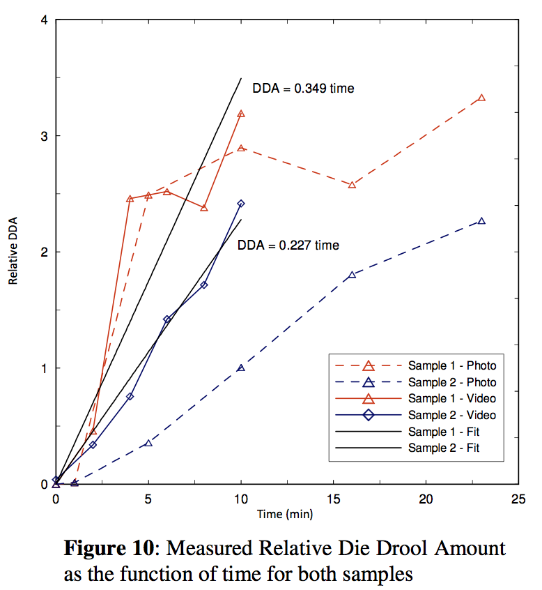
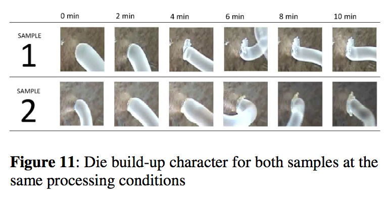
Digital photo camera shot collection (1 slide per 5 second) for Sample 1 and Sample 2 for the identical processing conditions described above is depicted in Figure 7. Surprisingly, the die build-up onset for both samples was found to be practically identical i.e. after 20s. With the aim to determine die build-up character intensity, the video camera collection for time evolution of die build-up phenomenon for Sample 1 and Sample 2 in large time scale was used (see Figure 8). It can clearly be seen that die deposit is, firstly, much faster for Sample 1 in comparison with Sample 2 and secondly, its character and shape is different. In more detail, Sample 1 and Sample 2 die deposit is similar to half of moon and a ring of flakes, respectively (see Figure 9 for more details). Calculated DDA amount as the function of time for both samples from both, photo camera and video camera data by the above mentioned digital image analyses is depicted in Figure 10. Here, the relative die deposit amount was calculated up to 10 minutes only where the die deposit thickness is small enough to justify 2D approximation applied for die deposit amount definition. From this graph, it is possible to determine die build-up speed as the relative die deposit change with the time. Clearly, the die deposit amount speed for Sample 1 is (0.349 / 0.227) ≈ 1.5 times faster than for Sample 2 (if the video camera data are used – see Figure 11 for more details). Also, one can clearly see that the obtained trends are consistent for both, photo and video camera data.
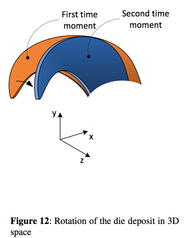
Final comment in this experimental part is related to the unexpected die drool amount decrease for Sample 2 between 6 and 8 min for video camera data (see Figure 10). This unexpected behavior is caused by other possible errors which can occur during digital image analysis if 3D effects are neglected. This is visualized in Figure 12 where it is demonstrated that the same piece of the material can have ‘different’ 2D surface area, if the rotation in the 3D space is not properly taken into account.
Mathematical modeling
Non-isothermal viscoelastic steady two-dimensional finite element simulations were performed by solving the wellknown mass, momentum and energy equations using the commercially available Compuplast software VEL 6.2. In this study, the modified White-Metzner (mWM) constitutive equation according to Barnes and Roberts (5) is employed. The non-isothermal mWM model is given by Eqs. (1) - (4).
where b is the temperature sensitivity parameter, T
r is the reference temperature, T is the temperature, d is the rate of deformation tensor, II
d is the second invariant of the rate of deformation tensor, τ is the stress tensor, ∇ τ is the upper convected time derivative of stress tensor. λ(II
d) is the deformation rate-dependent relaxation time and η(II
d) is the deformation rate-dependent viscosity, η
0 is zero shear-rate viscosity and λ
0, K
1, K
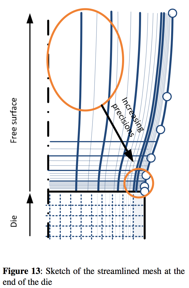
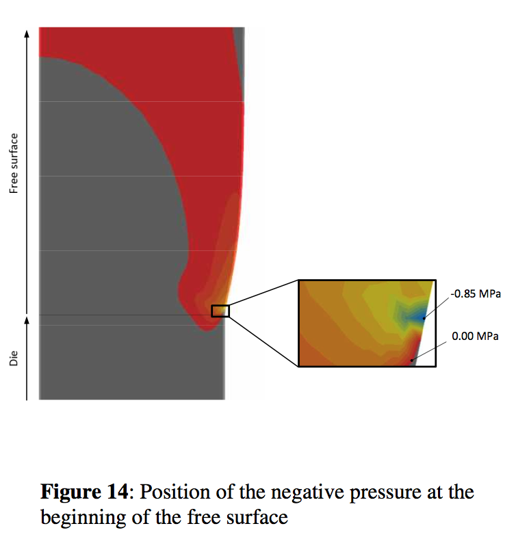
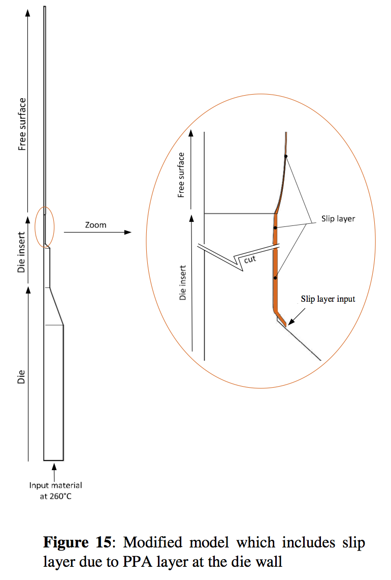
2, n,a are constants. The model parameters for the material used in this work are provided in Table 2. Special attention has been paid to the finite element mesh type which is capable to minimize possible errors which can arise due to not enough mesh density in the regions where the calculated variable such as velocity, pressure, stress and temperature are changed significantly (converging regions or die exit region where the free surface is developed). With the aim to fulfill the above stated requirements, the calculation has been made in two steps. In more detail, firstly, the shape and the free surface location have been determined by the use of automatically generated mesh. With the aim to minimize interpolation errors (which is typical for automatically generated meshes due to rather random element distribution) for velocity, pressure stress, temperature variables, the streamlined mesh has been utilized (see Figures 13). The calculated pressure field for the Sample 1 processing conditions is depicted in Figure 14 shows. In this case, the maximum value of the negative pressure which occurs at the area where the Sample 1 free surface is created is equal to -0.85MPa. For the flow modeling considering Sample 2 containing PPA, recently proposed effective continuum method has been utilized to capture the interaction between PP and PPA which causes the slip. This has been done by considering second inlet in the flow domain for the interaction layer as depicted in Figure 15. Mass flow rate and Newtonian viscosity were considered to be 0.01 kg/h and 100 Pa.s as suggested in (6) whereas the temperature has been assumed to be the same as the melt temperature at that region. The maximum value of the negative pressure which occurs at the area where the Sample 2 free surface is created is equal to -0.64 MPa. Clearly, the more stable PP Sample 2 has also smaller absolute value of the negative pressure comparing with the more unstable PP Sample 1. Therefore we can conclude that the negative value of the pressure at the die exit region is sensitive to the level of the die drool for the tested polypropylene resins under the chosen processing conditions.
Results and discussion
There remain the following questions which must be addressed with respect to the issue of negative pressure.
1)May the Newtonian fluid such as water possess negative pressure at the die exit region? This is possible because Newtonian fluids may also have negative pressure since in the free surface τnn - p = 0, i.e. as the Newtonian fluid is leaving the die, velocity rearrangement from parabolic to constant velocity profile occurs. This leads to the stretching of the Newtonian fluid in the tangential direction close to the free surface (τtt has a positive sign) whereas compression occurs in the normal direction (τnn has a negative sign). Therefore the stress at the free surface is only τnn - p = 0 if the pressure p is negative. Since polymer melts are viscoelastic and have memory, high viscosity and Trouton ratio, absolute values of -τnn and –p are much higher compared to the Newtonian fluids.
2) Can the die drool phenomenon be present during Newtonian flow? In general, die drool is a spontaneous accumulation of material at the die lip. In the case of a polymer melt, the viscosity of the accumulated material is reasonably high and material accumulation takes place within the extrusion time because gravity induced sag does not usually occur. In the case of a Newtonian fluid such as water, the accumulated material at the die exit sags immediately due to the low liquid viscosity and it can be seen that the face of the tube exit is wetted. This can also be viewed as a special case of the die drool phenomenon and negative pressure can be a factor promoting this.
3) Why was the pressure rather than stress state at the die exit region used for the die drool analysis in this work? In order to explore this point in more detail, it is necessary to clarify the effect of pressure in the flowing viscoelastic liquid (see recent papers by Dealy (7) and Han (8) for useful discussions). In most polymer processing flows, the deformation leads to anisotropy of the normal stresses and pressure as the scalar variable has no unique definition. In this case, suitable constitutive equations together with the mass, momentum and energy conservation laws have to be solved to determine the pressure. Therefore, the pressure can be viewed as the simple scalar variable helping us to understand the way in which viscoelastic polymer melts isotropically compensate shear and internal anisotropic normal stress rises due to imposed flow deformation history in the normal 3D space directions. Considering this the pressure can be understood to be a very useful and simple variable for theoretical analysis since it provides valuable information regarding the mechanism in which the stress is compensated during the flow. Due to the fact that die drool phenomenon is the consequence of the specific type of the polymer melt stress increase compensation occurring during flow, the pressure rather than stress has been utilized in this work. It should be mentioned that Tremblay (9), by using isothermal finite element analysis employing generalized Newtonian fluid, also obtained and discussed negative pressure at the die exit region. In his work, by using negative pressure only, the polymer melt fracture at the die exit (well known as the shark skin phenomenon) has been explained.
Conclusion
It has been demonstrated that the die build-up phenomenon can be obtained for both investigated polypropylene samples on the small laboratory extrusion line equipped by the specially designed die allowing controlled die exit region cooling even if the processing temperatures were higher than 200
oC. It has been demonstrated that the negative pressure theory with respect to die drool phenomenon can also be used for the polypropylene resins.
Acknowledgement: The support of the projects by the Ministry of Education CR (KONTAKT ME08090) is gratefully acknowledged.
References
1. J. D. Gander and A. J. Giacomin, Polym. Eng. Sci., 37, 1113 (1997).
2. F. Ding, L. Zhao, A. J. Giacomin and J. D. Gander, Polym. Eng. Sci., 40, 2113 (2000).
3. K. Chaloupkova and M. Zatloukal, Polym. Eng. Sci., 47, 871 (2007).
4. M. Zatloukal, K. Chaloupkova, K., M. Martyn, P. Coates: SPE ANTEC, Milwaukee, USA, 192 (2008).
5. H. A. Barnes and G. P. Roberts, J. Non-Newtonial Fluid Mech., 44, 113 (1992).
6. M. Zatloukal, J. De Witte, C. Lavalle, P. Saha, Plast. Rubber. Comp. 36(6), 248 (2007).
7. J. M. Dealy, Rheology Bulletin, 77(1), 10 (2008).
8. C. D. Han, Polym. Eng. Sci., 48, 1126 (2008).
9. B. Tremblay, J. Rheol 35(6), 985 (1991).
Key Word: Die drool, die build up, negative pressure.
