Multilayer Rheology Effects in Coextruded Structure Design
Joseph Dooley, Chunxia Costeux, Robert Wrisley, and Andrew Schlader - The Dow Chemical Company, Midland, MI
Abstract
Multilayer coextrusion is a process in which two or more polymers are extruded and joined together in a feedblock or die to form a single structure with multiple layers. This paper will discuss techniques for measuring experimental rheology data for monolayer and multilayer structures. These data will then be used to show the effects of multilayer rheology in the design of coextruded structures.
Introduction
Many polymers are extruded through various styles of dies to produce monolayer and multilayer products. Coextrusion is a common method used for producing multilayer structures. Coextrusion is a process in which two or more polymers are extruded and joined together in a feedblock or die to form a single structure with multiple layers. This technique allows the processor to combine the desirable properties of multiple polymers into one structure with enhanced performance characteristics. The coextrusion process has been widely used to produce multilayer sheet, blown film, cast film, tubing, wire coating, and profiles [1-6]. This paper will discuss techniques for measuring experimental rheology data for monolayer and multilayer structures. Experimental data will be shown on the viscosity of single polymer and coextruded polymer melts measured using a unique rheometer for coextruded structures. These data will then be used to show how the design of coextruded structures is affected by the viscosities of the individual layers and their placement in the structure.
Background
Many different types of monolayer and coextruded polymeric films and sheets are currently produced using different styles of dies. However, analyzing the flow of polymer melts through dies can be difficult due to the complex three dimensional flow patterns that exist [7-10]. This analysis becomes even more complex when multiple layers of different materials are introduced into the structure through coextrusion methods [11-17].
One of the difficulties in designing a new coextrusion die or analyzing the flow in an existing coextrusion die is determining the rheology of the coextruded structure. No commercial equipment is available to measure the rheology of a complex coextruded structure. The purpose of this work was to experimentally measure the rheology of monolayer and coextruded structures and to show how that information can be used for determining the effect of multilayer rheology on the design of coextruded structures.
Experimental
Two commercially available low density polyethylene (LDPE) resins manufactured by The Dow Chemical Company were used in the experiments: LDPE 722 and LDPE 641I. These resins will subsequently be referred to by letter designations to simplify the notation of the coextruded structures. These letter designations are Resin A for LDPE 722 and Resin B for LDPE 641I.
Resins A and B were chosen because they have significantly different viscosities based on their melt index (MI) values. Resin A has a melt index of 8 dg/min, (2.16 kg weight, 190ºC) while Resin B has a melt index of 2 dg/min. Even though these resins have different melt indices, their shear thinning characteristics are very similar.
Two types of experiments were run in this study. The first experiments were run to determine the viscosity of the individual resin components. The second series of experiments were run to determine the viscosity of coextruded encapsulated structures composed of multilayer combinations of the individual resins.
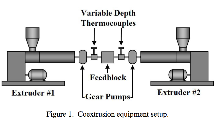
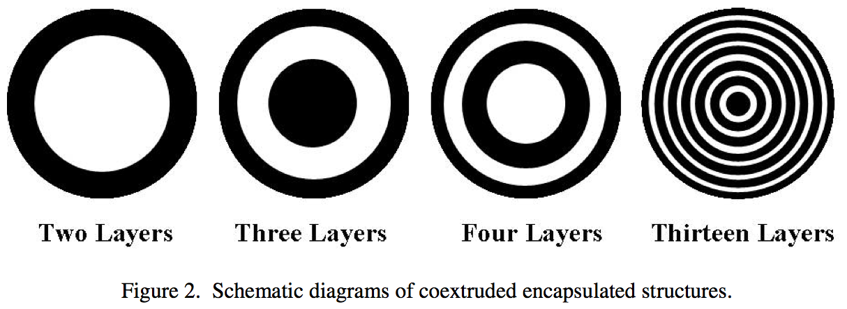
The coextrusion line used in this study for determining the viscosity of coextruded structures consisted of two 31.75 mm (1.25 inch) diameter, 24:1 L/D single screw extruders. A schematic diagram of the extrusion line set-up is shown in Figure 1. The extruders fed individual gear pumps to ensure uniform flow of the polymer melts to the feedblock and rheology dies. The gear pumps were attached to a feedblock by transfer lines that contained variable depth thermocouples to ensure consistent and uniform temperatures from the extruders. A feedblock was designed to produce coextruded encapsulated structures with the capability of varying the number of layers from 2 to 13. This is shown schematically in Figure 2. This feedblock allows evaluation of various coextruded structures with different layer arrangements and thicknesses.
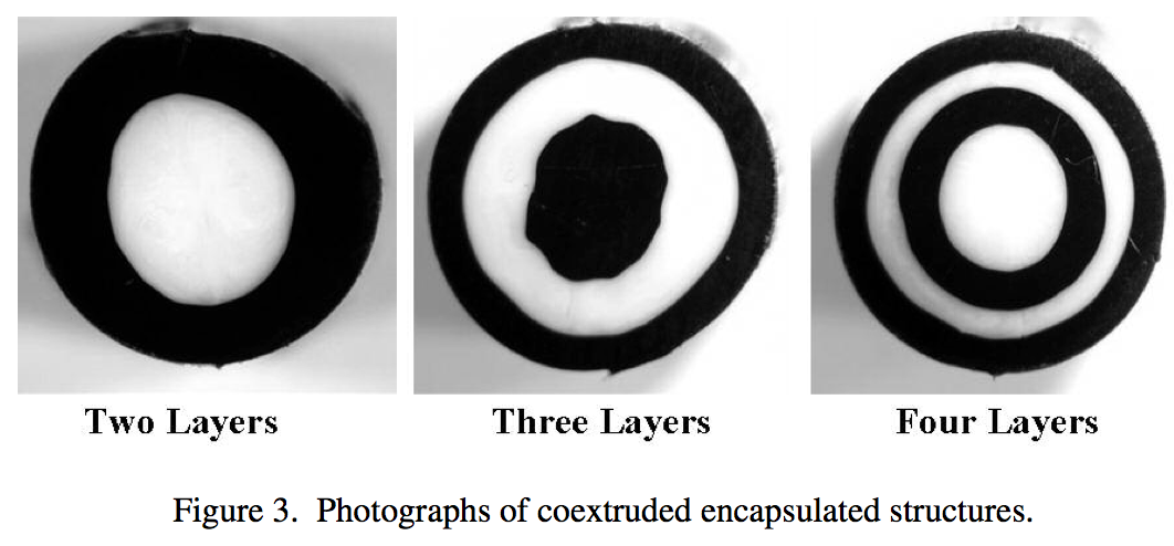
Examples of coextruded encapsulated structures are shown in Figure 3. Black and white pigments were added to these samples to show the skin and core layer thicknesses. For the experiments in which the rheology of the structures was actually measured, no pigments were added. Figure 3 shows photographs of samples with 2, 3, and 4 layers.
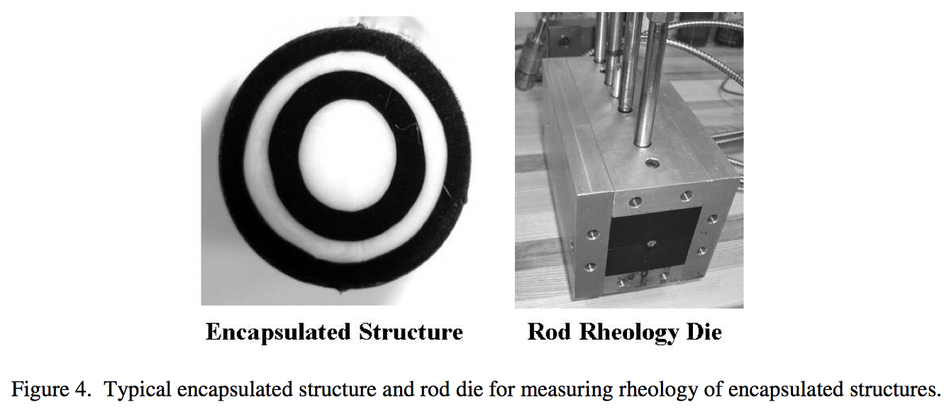
Attached to the exit of the feedblock was a rheology die that was fabricated with a circular cross section with a diameter of 7.9 mm (0.312 inch). This die had four pressure transducers spaced at 50.8 mm (2.0 inch) intervals down the length of the die. Figure 4 shows photographs of a typical 4 layer coextruded encapsulated structure on the left that would be extruded through the circular (or rod) rheology die on the right. The rod die is shown with the pressure transducers and the heating jacket installed.
For the rheology experiments, the coextrusion line was run with the two extruders and gear pumps producing set flow rates until steady-state conditions had been reached. At this condition, the pressures from the four transducers were recorded along with the measured total polymer flow rate and temperature. This procedure was repeated at several different flow rates so that the viscosity of the monolayer or coextruded structures could be determined at different shear rates and/or layer ratios.
Results
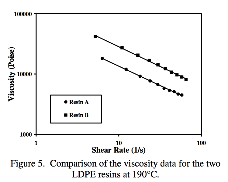
The experimental setup shown in Figure 1 was first run with each of the individual polyethylene resins (Resins A and B). Figure 5 shows the viscosity versus shear rate data generated for these polyethylene resins processed at 190ºC. These data show that these resins are significantly different in the magnitude of their viscosities at comparable shear rates.
The data generated for each resin were fit to a power law viscosity model and the resulting curves are shown in the Figure 5. Even though the magnitudes of the resins viscosities are significantly different at comparable shear rates, the slopes of the curves are very similar for these polyethylene resins. The slopes of these curves are related to the power law index, n. The power law indices for these resins at 190ºC are 0.36 and 0.35 for Resins A and B, respectively. Data have been reported previously [18] showing that this rheometer gives comparable results to a capillary rheometer when measuring the rheology of the individual resins.
The results throughout the rest of this paper will be based on 2, 3, and 4 layer coextruded encapsulated structures (like those shown in Figure 3) extruded through the rod rheology die.
An important point to remember when producing circular encapsulated structures is the fact that the layer thicknesses in the final structure will be different than in a planar structure. For example, a two layer planar structure composed of 50% by volume of Resin A and 50% by volume of Resin B would have equal layer thicknesses of layer A and B. However, a circular structure with Resin A encapsulating Resin B in which each material comprises 50% by volume of the structure would have a core layer thickness of approximately 70% and a total skin layer thickness of 30% (or 15% per side). This is solely due to the differences in the geometry of the circular versus planar samples.
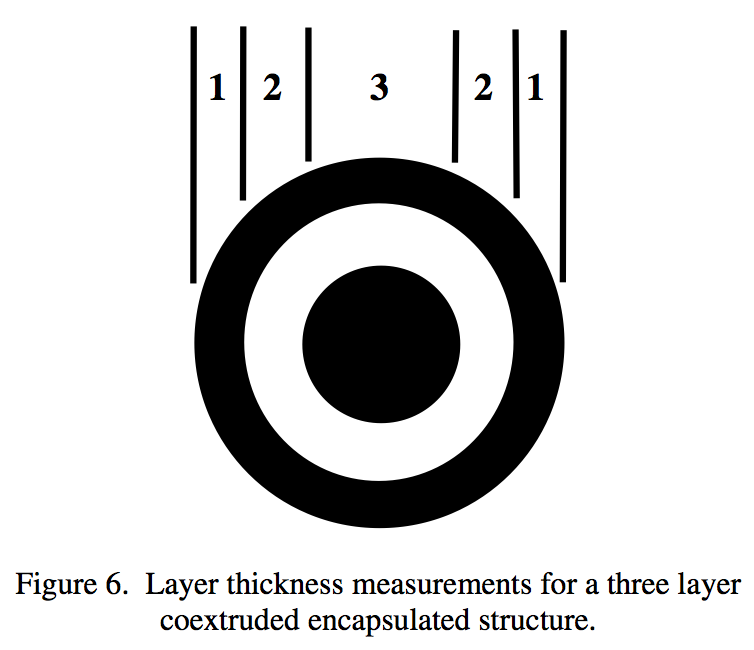
An example of this is shown in Figure 6. A three layer encapsulated structure was extruded through the rod die and measurements of the layer thicknesses in the extrudate were made. Figure 6 illustrates how 5 layer thickness measurements were made across the sample at the centerline. The three layer structure was formed by pumping the skin and core layers (black layers in the figure) at 40% by volume of the structure (divided evenly at 20% each) and the intermediate layer (white in the figure) at 60% by volume. The calculated thicknesses for layers 1 through 3 at the centerline are 5.3, 22.4, and 44.7%, respectively. The values we measured experimentally in the extrudate were 5, 23, and 43%, respectively. This shows very good agreement between the measured and calculated thickness values in the three layer encapsulated extrudate.
The next consideration in the rheology measurements of encapsulated structures is the fact that the layer thicknesses inside the rod die are not the same as the layer thicknesses in the extrudate. This is due to the fact that the velocity profile in the tube (parabolic) is different from the velocity profile in the extrudate (plug flow). This difference in velocity will cause a difference in the layer thickness in order to conserve mass. This is an important point since all of the measurements of pressure drop for the rheology calculations are done in the tube so the knowledge of the thickness of the layer there is critical.
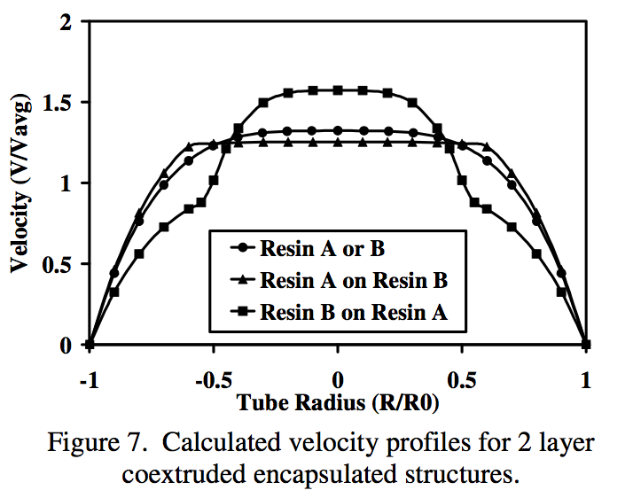
One final consideration is that since Resins A and B have different viscosities, the velocity profile in the tube will change depending on which material is used in each layer. This is illustrated in Figure 7 for a 2 layer coextruded encapsulated structure with equal volumetric flow rate in each layer. This figure shows the calculated dimensionless velocity profile (velocity/average velocity) in a tube for Resins A or B and combinations of A encapsulating B, and vice versa. Note that the curve for Resin A or B is a continuous curve with a flattened parabolic shape due to the shear thinning characteristics of these resins. Also, when Resin A encapsulates Resin B, the velocity gradient near the tube wall is higher but the central part of the flow is very flat. In contrast, when Resin B encapsulates Resin A, the velocity gradient near the wall is smaller and the velocity in the center is higher. The sudden changes in velocity in these curves are the locations of the interfaces between the layers. Also note that the interface locations change depending on which material is in the skin layer versus the core layer.
The next set of experiments consisted of extruding the two polyethylene resins in 2, 3, and 4 layer coextruded encapsulated structures with varying skin layer thicknesses. These experiments produced final extrudate structures with 5% to 40% skin layers of either Resin A or Resin B.
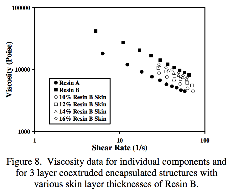
Figure 8 shows the viscosity versus shear rate data for Resins A and B along with 3 layer coextruded encapsulated structures with different skin layer thicknesses from 10 to 16% of Resin B. These skin layer thicknesses are the layer thicknesses inside the die. This figure shows that the viscosity curves for the encapsulated structures all lay between the extremes of the individual components. This figure also shows that as the skin layer thickness of Resin B increases, the resulting viscosity curve shifts toward the viscosity curve for Resin B alone. This result is consistent with those reported previously [8] and was also observed in the experimental results from the 2 and 4 layer structures.
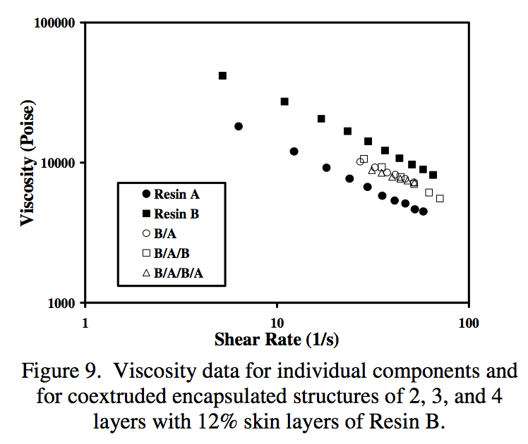
Figure 9 shows the viscosity versus shear rate data for Resins A and B along with data for 2, 3, and 4 layer coextruded encapsulated structures with 12% skin layers of Resin B in the die. The two layer structure produced consisted of a skin of Resin B on a core of Resin A (B/A). The three layer structure consisted of a skin of Resin B, a second layer of Resin A, and a core of Resin B (B/A/B). The four layer structure consisted of a skin of Resin B, a second layer of Resin A, a third layer of Resin B, and a core of Resin A (B/A/B/A).
Figure 9 shows that the viscosity curves for the encapsulated structures all lay between the extremes of the individual components. This figure also shows that the viscosity curves for the 2, 3, and 4 layer structures are all very similar. This result implies that at a constant thickness, the skin layer viscosity is the dominant factor controlling the viscosity of the structure even when there are a different number of layers with different viscosities below the skin layer.
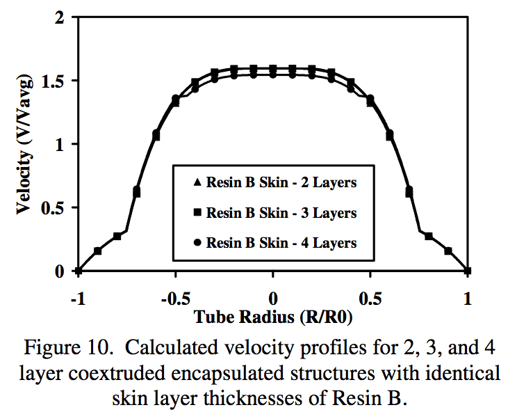
Figure 10 shows the calculated velocity profiles for 2, 3, and 4 layer coextruded encapsulated structures with identical skin layer thicknesses of Resin B. This figure gives some indication of why the skin layer tends to control the viscosity of the structure. Note in the figure that even though the velocities below the skin layers are different, the velocity gradient in the skin layers are very similar regardless of whether there are 2, 3, or 4 layers in the structure. This implies that the shear rate near the wall for these structures with the same material in the skin layers will be similar and produce similar viscosities for the structures.
Conclusions
A unique apparatus has been developed to measure the rheology of coextruded structures. This apparatus has been used to measure the rheology of monolithic and coextruded encapsulated structures. The results of these experiments show that the dominant factors affecting the rheology of coextruded structures are the viscosity and thickness of the skin layer. These findings are significant since they give more information on how to design a coextruded structure using the rheology of the different layers to approximate the rheology of the coextruded structure.
Acknowledgements
The authors would like to thank Adam Morris for his help in designing, constructing, and running experiments on the coextrusion rheometer.
References
1. L.M. Thomka and W.J. Schrenk, Modern Plastics, 49, 4, 62 (1972).
2. C.D. Han, J. Appl. Poly. Sci., 19, 7, 1875 (1975).
3. W.J. Schrenk, Plastics Engineering, 30, 3, 65 (1974).
4. J.A. Caton, British Plastics, 44, 3, 95 (1971).
5. L.M. Thomka, Plastics Engineering, 18, 2, 60 (1973).
6. C.R. Finch, Plastics Design Forum, 4, 6, 59 (1979).
7. C.I. Chung and D.T. Lohkamp, Modern Plastics, 53, 3, 52 (1976).
8. H.H. Winter and H.G. Fritz, Polymer Engineering and Science, 26, 543 (1986).
9. Y. Matsubara, Polymer Engineering and Science, 19, 169 (1979).
10. J. Dooley, SPE-ANTEC Technical Papers, 36, 168 (1990).
11. J. Dooley and B.T. Hilton, Plastics Engineering, 50, 2, 25 (1994).
12. J. Dooley and L. Dietsche, Plastics Engineering, 52, 4, 37 (1996).
13. J. Dooley and K. Hughes, TAPPI Journal, 79, 4, 235 (1996).
14. B. Debbaut, T. Avalosse, J. Dooley, and K. Hughes, Journal of Non-Newtonian Fluid Mechanics, 69, 2-3, 255 (1997).
15. J. Dooley, K.S. Hyun, and K.R. Hughes, Polymer Engineering and Science, 38, 7, 1060 (1998).
16. B. Debbaut and J. Dooley, Journal of Rheology, 43, 6, 1525 (1999).
17. P.D. Anderson, J. Dooley, and H.E.H. Meijer, “Viscoelastic Effects in Multilayer Polymer Extrusion,” Applied Rheology, 16, 4, 198 (2006).
18. J. Dooley, SPE-ANTEC Technical Papers, 53, 2383 (2007).
Keywords: Rheology, coextrusion, encapsulation, die design.
Return to
Best Papers.