An Experimental Study of the Factors Affecting the Layer Thickness Uniformity of Coextruded Structures
J. Dooley and E. Stout - The Dow Chemical Company
IntroductionCoextrusion is a process in which two or more polymers are extruded simultaneously and joined together to form a single structure with multiple layers. This technique allows the processor to combine the desirable properties of dissimilar polymers into one structure. The coextrusion process has been used to produce multilayer sheet, blown film, cast film, tubing, wire coatings, and profiles (1-6).
In this study, a specific feedblock and sheet die combination was used to determine the effect of different extrusion and geometric variables on the layer thickness uniformity of a two layer sheet product. A designed experiment was developed to guide the experimentation and to statistically analyze the results.
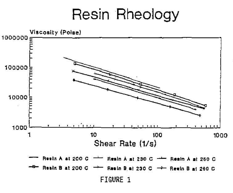
EXPERIMENTALThe two resins chosen for this study were an ABS (Acrylonitrile-Butadiene-Styrene) polymer (Resin A) and an AES (Acrylonitrile-EPDM-Styrene) weatherable polymer (Resin B), Resin A was used as the substrate and Resin B was applied as a cap layer with a target "thickness of 10%" of the total structure. These two resins were chosen because they exhibit similar rheological characteristics over the temperature range studied. The viscosity curves for these resins are shown in Figure 1.
The coextrusion line used in this study consisted of a 114.3 mm (4.5 inch) diameter, 30:1 L/D single screw extruder for the substrate resin and a 63.5 mm (2.5 inch) diameter, 24:1 L/D single screw extruder for the cap resin. The sheet die was a 1.42 m (56 inch) wide Ultraflex R75 die Manufactured by Extrusion Dies, Inc. (EDI). The feedblock and flow-shaping inserts were designed and fabricated by the Mechanical Development and Operations Group of The Dow Chemical Company. The feedblock inserts were designed to restrict the flow of the cap material to the edge of the sheet. The geometry used in these inserts joins the two polymer layers in the feedblock in the configurations shown in Figure 2. Insert "A" was used as a control and represented no flow restriction of the cap with respect to the substrate (a 100% slot opening). Inserts "B" and "C" restricted the flow of the cap layer by narrowing the flow path widths to 67" and 34" of insert "A", respectively.
This study utilized a Box-Behnkin type designed experiment. This type of design will produce a mathematical description of the response variable as a function of the independent variables, including any curvature that may be present. This study contained three independent variables (feedblock slot shape, cap layer melt temperature, and cap layer extruder screw speed) and the response was the uniformity of the cap layer thickness as measured by the standard deviation from the mean cap thickness. This experiment also contained multiple center points to determine reproducibility.
In these experiments, the cap layer melt temperature was varied from 220 degrees C to 235 degrees C while the cap layer screw speed varied from 60 to 80 RPM. The target sheet thickness was 2.8 mm (0.110 inches) at an overall extrusion rate of 455 kg/h (1000 pounds/h). The substrate screw speed and celt temperature were held as constant as possible throughout the experiments. There were no die deckles used and the restrictor bar was maintained in a retracted position during the experiments.
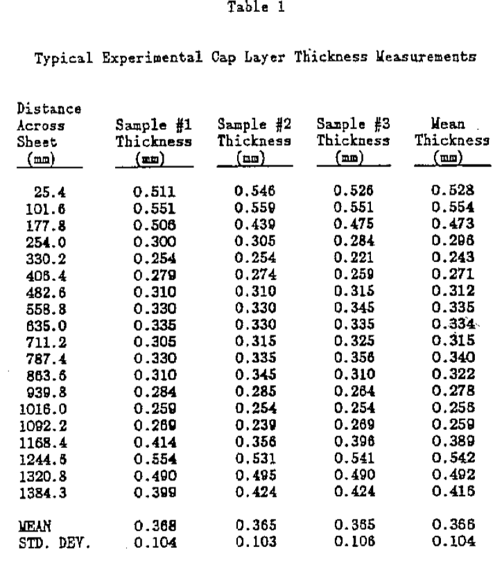
The cap layer thickness distribution for each experiment was determined by testing three sheet samples collected during that experiment and averaging the results. The cap layer thicknesses were measured with an optical microscope every 76.2 mm (3 inches) across each sample. A typical set of measurements for an experiment including the means and standard deviations is shown in Table 1.
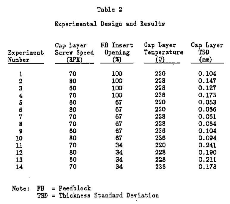
ResultsThe experimental design used and the calculated results from the sheet thickness measurements are shown in Table 2. Analyzing these results statistically reveals that the most important factor (of those studied) affecting the cap layer thickness distribution was the insert slot geometry. The cap layer melt temperature was found to have some effect on the distribution while the cap layer screw speed was found to be statistically insignificant.
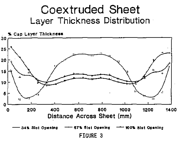
Figure 3 shows the effect of the three insert geometries on the coextruded sheet layer thickness distribution. This figure is plotted as the distance across the sheet versus the cap layer thickness expressed as a percentage of the total sheet thickness. The 100% slot opening curve represents the control and shows that the cap layer material flowed more to the edge of the sheet than to the center. On the other hand, the 34" slot opening curve shows that this insert moved most of the cap to the center of the sheet. Of the three inserts studied, the cost uniform distribution of cap layer material across the sheet was produced by the 67% slot opening insert. However, this insert still does not appear to be the optimum for uniformly spreading the cap layer across the sheet.
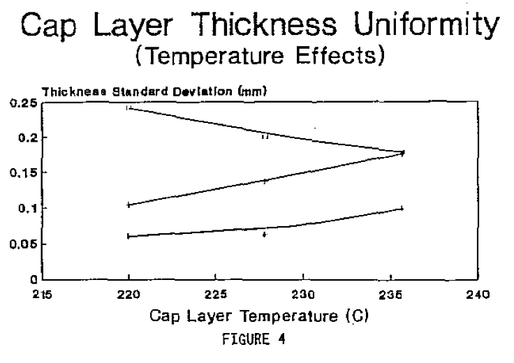
The effect of cap layer temperature on the layer thickness uniformity is shown in Figure 4. This figure shows the standard deviation of the mean cap layer thickness as a function of the cap layer temperature for each insert geometry. These curves show that the inserts with 67% and 100% slot openings produced a higher standard deviation value as the cap temperature was increased. However, the standard deviation value decreased with increasing temperature for the 34% slot opening insert.
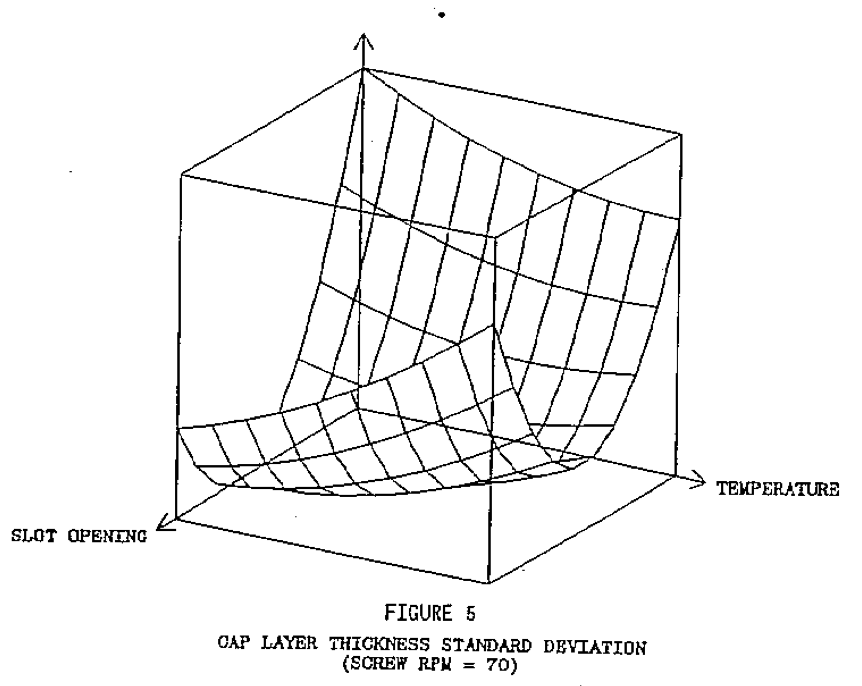
A statistical model was generated using the results of these experiments to show the effects of the independent variables (over the range studied) on the cap layer thickness uniformity. Figure 5 is a plot of this statistical model at a constant screw speed showing the effect of the insert slot opening and cap layer temperature on the cap layer thickness standard deviation. This figure shows similar results to Figure 4 but now as a continuous function instead of discrete points. This statistical model had a correlation coefficient (r
2) of 0.96 indicating that most of the variability in the data could be explained by the model.
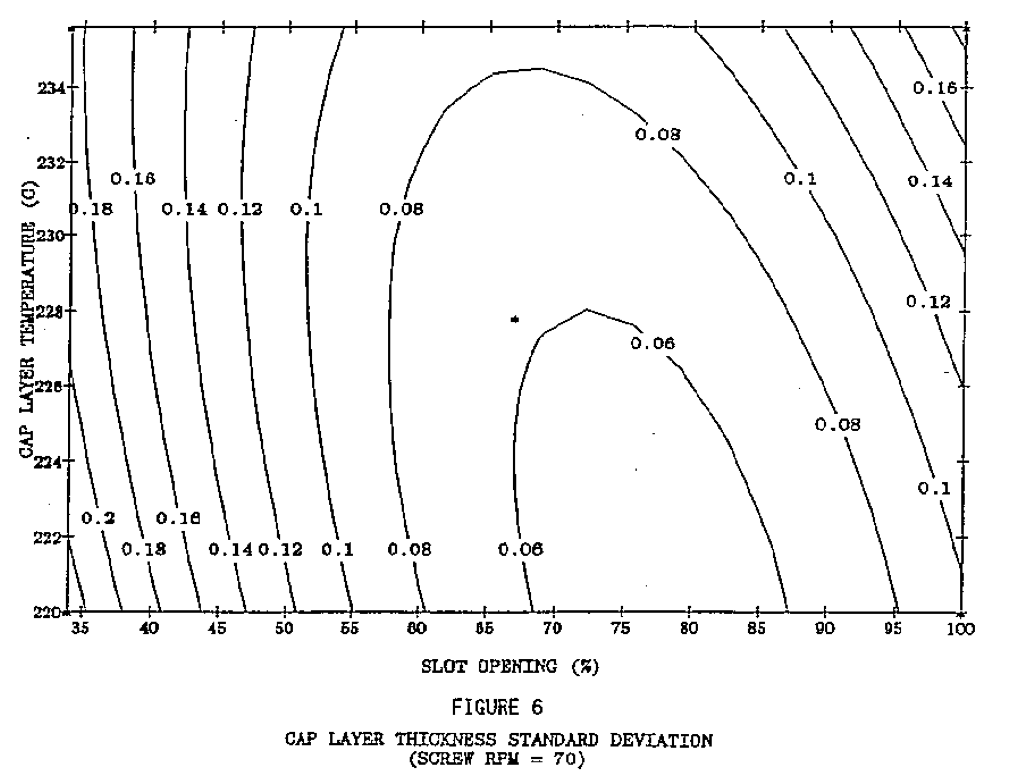
Another method to look at these results is shown in Figure 6. This plot shows constant contours of cap layer thickness standard deviation as a function of insert slot opening and cap layer temperature. Since the statistical model is a continuous function, it can be used to predict an optimum set of conditions that will minimize the cap layer thickness standard deviation. The model predicted the minimum thickness deviation would occur with an insert slot opening of 80%, a screw speed of 61 RPM, and a cap layer temperature of 220 degrees C. It should be noted that this statistical model is intended for use within the domain of variables tested and should not be used to extrapolate outside of those limits.
CONCLUSIONS
It was determined that for the specific feedblock/die combination studied, the most significant variable affecting the thickness uniformity of the cap layer in a two layer sheet was the feedblock insert geometry. The cap layer melt temperature also had a significant effect on the thickness uniformity. The experimental data showed that a significant improvement in the overall sheet layer thickness uniformity could be made by changing the geometry of the feedblock insert.
Statistically modeling the thickness uniformity of the cap layer based on the different extrusion and geometric variables in the system was very beneficial in determining optimum processing conditions. This methodology can also be used by processors to help optimize other aspects of their extrusion operations.
REFERENCES1. L.M. Thomka and W.J. Schrenk, Modern Plastics, (April 1972)
2. C.D. Han, J. Appl. Pol. Sci., 19, (1975)
3. T.J. Schrenk, Plastics Engineering, (March 1974)
4. J.A. Caton, British Plastics, 3, (1971)
7. L.M. Thomka, Package Engineering, 18, (Feb. 1973)
6. C.R. Finch, Plastics Design Forum, 59, (Nov./Dec. 1979)
DISCLAIMERNothing herein is meant to imply a license or other right to use the information contained in this paper as respects any patents of The Dow Chemical Company or others, or that the practice of the information will be suitable for any particular purpose.
Return to
Best Papers.