Analysis of Extrusion Characteristics of LLDPE
Chris J. Rauwendaal - Raychem Corporation
IntroductionIt has been observed in many instances (1-5) that the extrusion behavior of LLDPE is substantially different from other polyethylenes, such as LLDPE or HDPE. Two of the major problems in extrusion of LLDPE are high power consumption and high stock temperatures.
Various solutions have been suggested (1, 3, 4); however, there seems to be little consensus as to what the proper corrective action should be. There is a particular lack of agreement concerning the
questions of the optimum screw design for LLDPE. In this paper, we will take a careful look at the polymer properties of LLDPE that affect the extrusion behavior and compare these to a LDPE and HDPE. We will then report on the extrusion characteristics of these three polymers in actual extrusion experiments. Finally, we will present an engineering analysis of the extrusion process, taking into account the special characteristics of LLDPE. It will be shown that the typical extrusion problems of LLDPE can be predicted quantitatively if the right polymer properties are known. From this more basic understanding of the source of the problems, the proper solutions in terms of operating conditions and screw design become quite obvious.
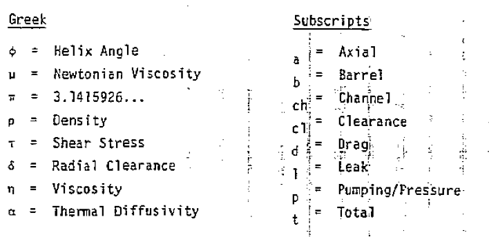
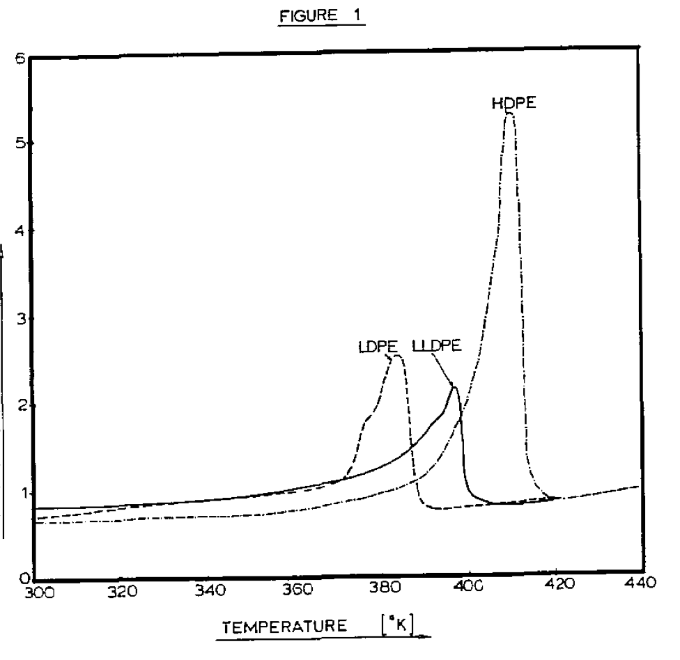
Polymer PropertiesBased on extrusion theory, three types of data are required to evaluate the extrusion characteristics of any polymer. These are data on i) density, ii) thermal properties, and iii) frictional and viscous properties. In a comprehensive analysis, all three types of data should be considered. The three polymers analyzed in this study are LDPE (DFD 6040 by Union Carbide), LLDPE (DFDA 7547 by Union Carbide), and HDPE (Marlex 6003 by Phillips). All the data are shown in Table I. In addition, Figure 1 shows the specific heat as a function of temperature for all three polymers.
The density and bulk density of LDPE and LLDPE are quite close. HDPE is higher in density and bulk density, largely because of its high crystallinity. In terms of thermal properties, LLDPE is very similar to LDPE. Therefore, one would expect the thermal behavior in an extruder to be very similar as well, all other factors being constant. The same is true for the frictional properties of LDPE and LLDPE. Thus, the solids conveying characteristics in an extruder would be expected to be quite similar for these two polymers. In the melt flow properties, some significant differences can be seen. The viscosity at low shear rates for LLDPE is considerably lower than for LDPE or HDPE; at high shear rates the opposite is true. LLDPE is much less shear thinning than LDPE, but also less than HDPE. The power law index of LLDPE is almost twice as high as LDPE and about 20 percent higher than HDPE.
Based on the polymer properties, one would expect the plasticating and melt conveying in an extruder to be significantly different for LLDPE as compared to LDPE and HDPE. The plasticating process will also be affected because the viscous heat generation in the thin melt film between the barrel and the solid bed Will most likely be substantially higher for LLDPE. One would, therefore, expect melting to be completed earlier, contributing to a rise in stock temperature.
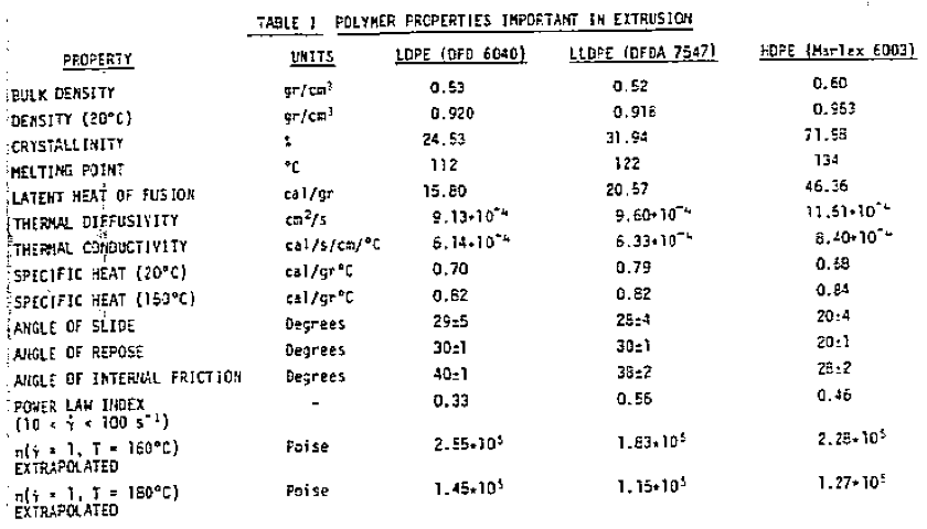
Extrusion ExperimentsIn order to evaluate the actual extrusion characteristics of the three polyethylenes, the three polymers were extruded on a 1.5-inch extruder. The extruder is a 24 L/D machine made by Davis-Standard. The polymer was extruded through a coat-hanger die, producing a sheet 6 inches wide and 0.020 inch thick. Each polymer was extruded at 40 and 60 rpm; each experiment was repeated on a different day in order to assess the reproducibility of the data. The process parameters are shown in Tab1e II.
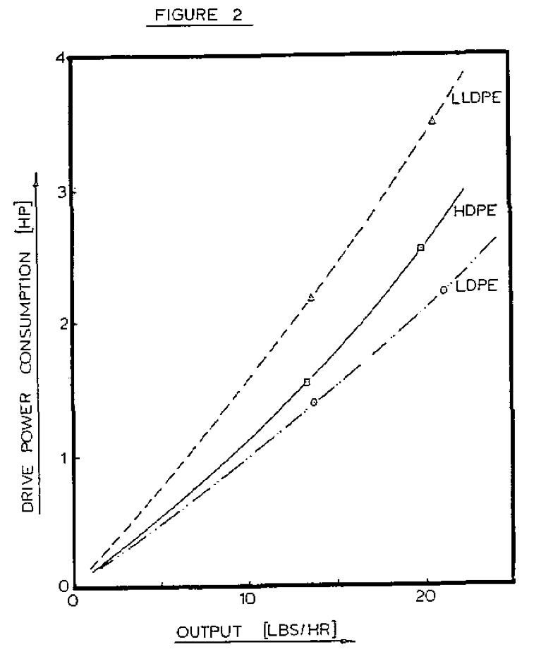
In looking at the data, two points are quite noticeable. Both the diehead pressure and the motor load for LLDPE are considerably higher than for LDPE, but also higher than HDPE. This is shown in Figure 2. This is another indication that the thermal properties or density are not responsible for the unusual extrusion behavior of LLDPE. The specific energy consumption (SEC) for all three polymers is relatively independent of output. The average SEC for LLDPE is 56 percent higher than LDPE and 34 percent higher than HDPE - these are very large differences indeed!
The diehead pressure of LLDPE is about 54 percent higher than LDPE and 35 percent higher than HDPE. The relative differences in motor load and diehead pressure are very close. It seems safe to assume that they have the same origin. The output per RPM in all cases is about the same. Thus, the average residence time of the polymers should be about the same as well. Therefore, the increased power consumption can only be explained by the fact that the overall level of shear stress in LLDPE must be considerably higher than either LDPE or HDPE,
AnalysisFrom the flow properties, it is not immediately obvious that LLDPE should cause a higher motor load in extrusion. At low shear rates, the viscosity of LLDPE is lower and at high shear rates, the viscosity of LLDPE is higher than LDPE and HDPE. The cross-over point occurs at a shear rate of about 10 to 50 sec
-1, It is clear, therefore, that the high power consumption with LLDPE is largely determined by shearing at rates considerably higher than 10 sec
-1. The power consumption in the screw channel for a Newtonian fluid can he written as (7-10):
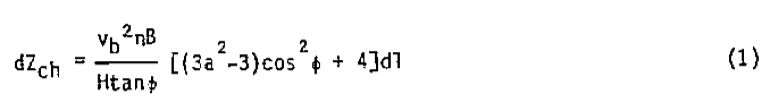
where variable "a" represents the ratio of pressure flow to drag flow.
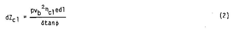
The power consumption in the clearance between screw flight and barrel is:
The power required to raise the pressure is:

The total power consumption for melt conveying is:

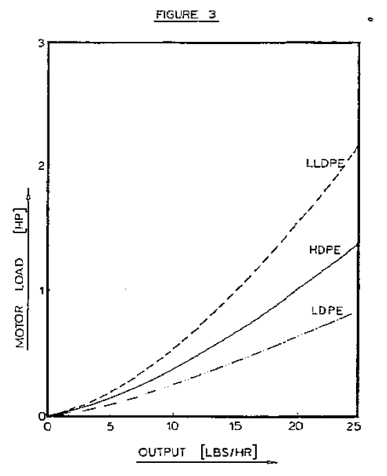
If the viscosity in the screw channel and in the clearance is evaluated, locally, by means of a power law relationship, the output versus power consumption can be calculated as a function of power law index. Figure 3 shows the predicted power consumption for the three polymers as a function of output. The relative differences in power consumption from the extrusion experiments, Figure 2, are in good agreement with the predicted values, shown in Figure 3.
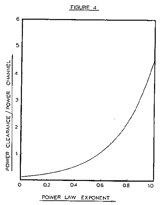
The ratio of power consumption in the clearance to the power consumption in the channel is strongly dependent on the viscosity ratio and, thus, on the power law index. This is shown in Figure 4. The ratio of power consumption in clearance to the power consumption in the channel (power ratio) increases with increasing power law index. For a Newtonian fluid the power ratio is predicted to be 4.5:1!! This means that more than 80 percent of the power is consumed in the clearance. In the case of LLDPE with a power law index of 0.56, about 50 percent of the power is consumed in the flight clearance.
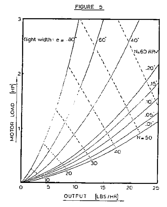
Obviously, the geometry of the flight clearance is of critical importance to the power consumption. The three important geometrical parameters are flight width, helix angle, and radial clearance. The effect of flight width is shown in Figure 5. Reducing the flight width from 0.200 inch to 0.100 inch causes a reduction in power consumption of almost 30 percent! Utilizing a flight width smaller than the standard 0.10 can clearly yield substantial reductions in power consumption and temperature build-up.
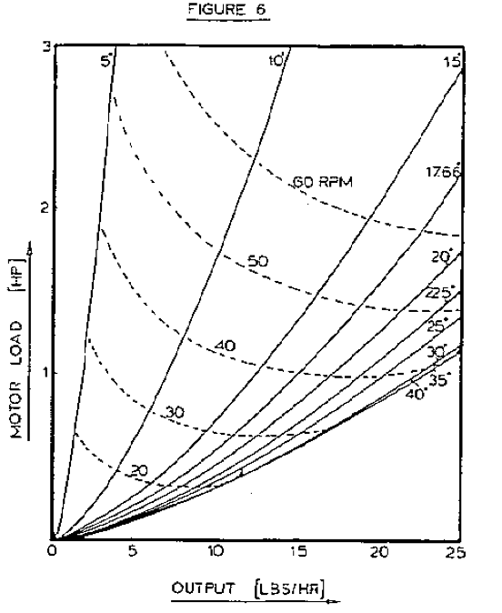
The effect of the helix angle on power consumption is shown in Figure 6. The power consumption reduces with helix angle up to a certain optimum value, from then on the power consumption increases with helix angle. The data in Figure 6 is only valid for one set of conditions. Therefore, it would be useful to develop a general method to detemine the optimum helix angle for power consumption. Since both power consumption and temperature build-up are of concern, the specific energy consumption should be minimized. The specific energy consumption (SEC) is the mechanical energy expended per unit mass of material. Thus, the SEC is responsible for the temperature build-up in the polymer by frictional and viscous dissipation of energy supplied by the extruder screw. A general expression of the optimum helix angle for SEC can be obtained by setting:
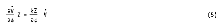
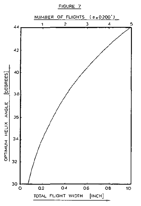
This becomes clear when one realizes that SEC is the ratio of power consumption (Z) to output (V). The actual expression can be found in (11). There is not an apparent simple, analytical solution to this equation. Thus, a numerical technique should be employed to find the optimum helix angle. A Newton-Raphson scheme yields a solution generally within five or six iterations. The actual value of the optimum helix angle is rather insensitive to pressure gradient and radial clearance, but fairly sensitive to the flight width or number of flights. This is shown in Figure 7.
Similar to the helix angle, there is also an optimum value of the radial clearance for which the SEC is minimized. A general expression for the optimum radial clearance can be determined from:

The actual expression can be found in (11). Again, there is no apparent analytical solution, and a numerical technique should be used to find the solution. For the 1.5 inch extruder, used in the experiments, the optimum clearance for LLDPE is found to be 6.63 mils, with the pressure rise over the metering section being 2000 psi. A general industry practice is to make the radial clearance about one mil per inch of screw diameter. Thus, the optimum clearance is much larger than the standard clearance! Determining the optimum clearance this way has the advantage that the clearance is determined from a functional analysis and not just simply determined by mechanical considerations.
Optimum GeometryThe optimum geometry of the screw flight is determined by the flight width, helix angle, and radial clearance for 'which the SEC is minimized simultaneously. The theoretically optimum flight width in the example is about 10 mils (11). Thus, considerations of mechanical strength will clearly limit the minimum flight width that can be tolerated. The stresses in the screw flight are directly proportional to the flight height and inversely proportional to the flight width Squared. Taking this into account, a more sensible guideline for the flight width in the metering section can be formulated:
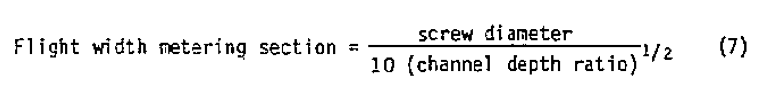
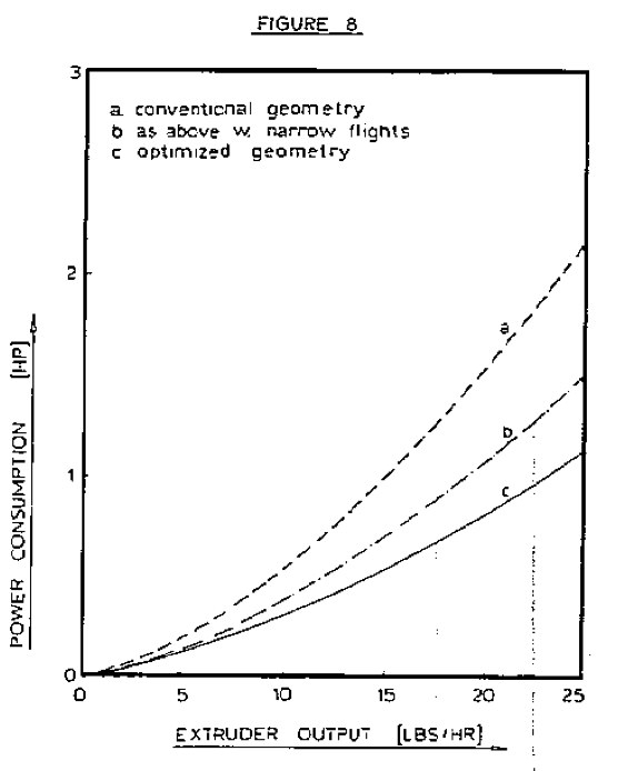
In the example, this guideline gives a flight width in the metering section of 0.090 inch. This is considerably narrower than the 0.200 inch flight width in the actual screw design. With this flight width, the optimum helix angle with LLDPE becomes 29 degrees and the radial clearance 6 mils. Figure 8 shows the power consumption for the screw with the conventional geometry and the screw with the optimized geometry. A substantial reduction in power consumption is obtained by optimizing the flight geometry; the reduction is about 45 percent! The effect of changing only the flight width is also shown in Figure 8. Reduction of the flight width causes about a 30 percent drop in SEC. Thus, by making a minor modification to an existing screw, one could achieve a significant reduction in power consumption.
It should be noted that the power consumption was only calculated in the melt conveying zone. The calculations were performed over an axial length of 100. Thus, it is to be expected that the total power consumption will be about twice the calculated power consumption. This is confirmed by comparing the actual total power consumption (Figure 2) to the predicted power consumption of the melt conveying zone (Figure 3),
ConclusionsThe high power consumption of LLDPE resins is primarily due to the high absolute level of the melt viscosity and the low degree of pseudoplasticity. LLDPE is much less shear thinning than LDPE, but also less than HDPE. The melt conveying zone is, to a large extent, responsible for the high power consumption. Power predictions based on just melt conveying do indeed show the same relative differences as observed in actual experiments. The experiments are done with a LDPE, a LLDPE, and a HDPE. In all cases, the LLDPE polymer showed the highest motor load.
A large fraction of the motor power is consumed in the clearance between flight and barrel. This fraction increases as the degree of pseudoplasticity of the polymer melt decreases. With LLDPE about 45 percent of the power is consumed in the clearance when a standard screw design is used; with LDPE this is about 25 percent. Particular attention should be paid to the geometry of the flight if the power consumption needs to be reduced.
Expressions were derived from which the optimum helix angle and radial clearance can be determined. The minimum flight width is determined by its mechanical strength. A guideline for the flight width in the metering section is given. The optimum values for helix angle, clearance, and flight width deviate considerably from values considered standard in the industry. Comparing the optimized geometry to the conventional geometry, the drop in power consumption is about 45 percent in the case of LLDPE. Thus, it is clear that substantial power reductions can be obtained by proper design of the extruder screws.
It should be clear that by reducing the SEC, the viscous heat generation in the polymer will be reduced as well. Thus, reducing the power consumption will also reduce the problem of high stock temperatures.
Reference1. E. W. Veazey and J. E. Suazo, SPE Tech. Papers (PACTEC), 6, 129 (1981).
2. L. Hoover-Siegel, Plast. World, p. 70, Jan. (1982).
3. S. J. Kurtz, L. S. Scarola and J. C. Miller, Plast. Eng., 45, June (1982).
4. W. Kurzbuch, SPE Tech. Papers (ANTEC). 28, 199 (1982).
5. D. Constantin, SPE Tech. Papers (ANTEC), 28, 206 (1982).
6. J. A. D. Emmanuel and l. R, Schmidth, SPE Tech. Papers (ANTEC), 27. 672 (1981).
7. E. C. Bernhardt, ed., "Processing of Thermoplastic Materials", Krieger, Huntington, NY, (1959).
8. W. L Gore and J. M. McKelvey, "Theory of Screw Extruders", ch. 16 of, Rheology, Vol. 3, edited by F. R. Eirich Academic Press (1960).
9. J. M. McKelvey, "Polymer Processing " John Wiley & Sons, NY (1962).
10. Z. Tadmor and I. Klein, "Engineering Principles of Plasticating Extrusion'', van Nostrand Reinhold Comp., NY, (1970).
11. C. J. Rauwendaal, Paper submitted to Polym. Eng. Sc., Dec. (1982).
Return to
Best Papers.